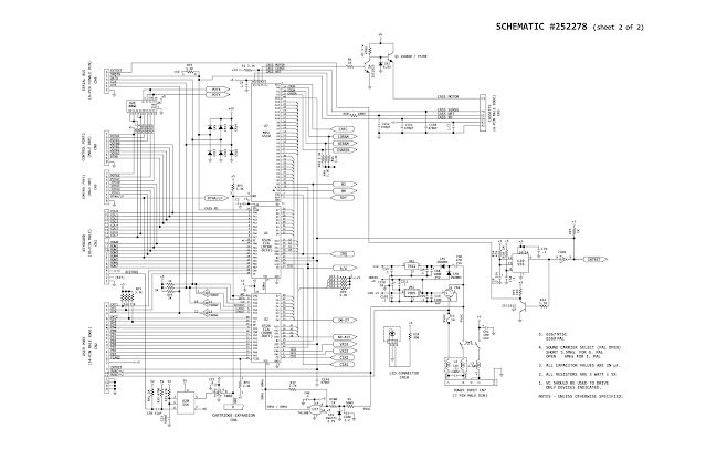
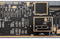
Due to the poor quality of scans available elsewhere, I have remastered these diagrams and provide them here for your convenience. These images have enough resolution to be printed very large, should you desire.
BOARD LAYOUT (click for full sized image - 6288 x 3090 pixels):
SCHEMATICS (Click for full sized images - 6932 x 4516 pixels)
#252278 1 of 2
#252278 2 of 2
MODULATOR #251696 (Full Sized Image - 3500 x 3221 pixels)
NB - the modulator schematic is problematic. Some Inductor values are missing in the original service manual and I have not been able to find any alternative information to fill in these blanks. The schematic is therefore provided "as is" knowing these omissions are present.
As always, every effort has been made to make these error free, however, should you find an error I have missed, please contact me and I will be more than happy to fix and upload a revision.


