INTRODUCTION
The JaF Sandwich is a replacement for the RF Modulator in a Commodore 64. More specifically, I have designed the JaF Sandwich to be used in my modern 250466 recreation (clone) of the Commodore 64, called the SixtyClone by Rob Taylor. Rob's SixtyClone is an exact copy of the original Commodore revision 250466 board and does not come with any RF Modulator functionality. Thus, if building one of these clones, in order to get a video signal you must source either an original RF Modulator on the second-hand market, or a modern replacement. There are many modern replacements available, developed and manufactured by enthusiasts so they come and go. The JaF Sandwich is one I designed myself.
CRITICAL POINTS TO NOTE
- The JaF Sandwich has never been tested in any other version of the SixtyClone other than the 250466 version.
- The JaF Sandwich has never been tested on an original Commodore board of any variety.
- The JaF Sandwich has never been tested with NTSC.
- The JaF Sandwich will categorically not work with either the 250469 (aka "short") board or the old 326298 assemblies.
- The JaF Sandwich has never been tested in a breadbin style case.
Given these caveats, I therefore make no guarantees that the JaF Sandwich is suitable for your needs. I do not have limitless funds; have no sponsorship, advertising, Patreon or Ko-fi income, and the costs I would incur obtaining different working C64 boards for such tests, is simply beyond my means.
WHAT DOES THE C64 RF MODULATOR DO?
In very simple terms, the original RF Modulator found in Commodore 64s is designed to do four things:
- Amplify the Chroma (Color) output from the VIC-II chip and output this signal via the standard Audio/Video port.
- Amplify the Luma/Sync (Luminosity and Synchronisation) output from the VIC-II chip and output this signal via the standard Audio/Video port.
- Merge the amplified Chroma, Luma/Sync signals to create a Composite signal and output this via the standard Audio/Video port.
- Merge the amplified Chroma, Luma/Sync and also add the Audio signal from the SID chip to create an RF signal and output this via the RCA Jack.
From this list, number 4, generating the RF Output (i.e. the modulator function) is, generally, no longer required. This output was designed to be connected to the aerial socket of a CRT TV or Monitor. On modern TV's this functionality is awkward to use at best, or impossible at worst and will result in, arguably, terrible picture quality.
With modern TVs, which generally require an HDMI signal, it is possible to use either the Chroma and Luma/Sync signals, or the Composite signal coming out of the Audio Video port on the C64 and with an external upscaler (of which there are many varieties, bad and good, expensive and cheap), convert this to an HDMI signal.
WHAT DOES THE JaF SANDWICH DO?
For the reasons above, the JaF Sandwich has dropped everything to do with the generation of the RF signal, and just deals with Chroma, Luma/Sync and Composite signals. This functionality has been derived from the original Commodore schematics with a few quality of life improvements.
Now, whilst this works reasonably well with a modern HDMI TV, it is compromised. There is very little one can do to completely remove artefacts from these old video signals when being pushed through HDMI. They were simply never designed to work that way. As it is then, you can either live with these compromises (jailbars and color fringing being the most common culprits), or you have to embrace some modern technology.
In recent years, new hardware has been developed for the Commodore 64 to improve the picture quality. One such development, and the one I'm predominantly interested in here, is the VIC-II-dizer. This is a small PCB which is designed to sit between the Commodore 64 mainboard, and the original VIC-II chip. It listens to the video signals being generated in the VIC-II and generates its own video signal (called LumaCode) which can be converted (via an external decoder called the RGBtoHDMI) into an HDMI signal.
The VIC-II-dizer has been designed specifically to attach to an original C64 RF Modulator. It utilises the RCA Jack in the original modulator, and after cutting a single cable, reuses this jack to output the shiny new LumaCode signal. My 250466 SixtyClone board does not have an original RF Modulator, therefore does not have an RCA Jack, and thus cannot neatly use the VIC-II-dizer. I have therefore specifically designed The JaF Sandwich C64 RF Modulator Replacement to remedy this.
The JaF Sandwich provides a simple pass-through connection, allowing the LumaCode signal from the VIC-II-dizer to be passed to an RCA Jack. In turn, the signal passes from this RCA Jack, out of the machine and uses the standard RCA Cable provided with the RGBtoHDMI to convert to an HDMI signal and then on to a modern TV.
Because I was incorporating an RCA Jack anyway, I have also incorporated the ability to use an experimental function of the Kawari Mini, a modern and complete replacement for the VIC-II developed by Randy Rossi. By using an experimental firmware it is possible for the Kawari Mini to generate LumaCode (exactly like the VIC-II-dizer) and again, by use of the RGBtoHDMI, produce an HDMI video signal. Further details are below.
If you have some soldering experience it is a reasonably straightforward build with only a couple of awkward elements. I am a slow, but competent solderer; it takes me about 3 hours to build one sandwich so it's a bit of a chore, but the upside is I end up with a perfectly capable, multi-function RF Modulator replacement that is completely modular meaning it can be removed and replaced with no further soldering/desoldering at all.
GERBERS (REVISION G)
These are free for non-commercial use.
Click the image to download the Main-board Gerber files:
| Main-board |
Click the image to download the Top-Board Gerber files:
Click the image to download the Daughter-Board Gerber files:
COMPONENTS (BILL OF MATERIALS)
Click image below to download Bill of Materials PDF:
| BOM |
Note: some of the images used below are from early prototypes and not identical to the final design, however, this does not change the build principle.
Printed Circuit Boards

- JaF Sandwich top-board
- JaF Sandwich daughter-board
- JaF Sandwich mainboard
The Gerbers are available above. When ordering the daughter-board, you must remember to select a 1.2mm thick board and to select the crenelated holes option. This latter requirement will unavoidably increase the price.
Note: the BOM (in PDF above) contains DigiKey part numbers (where applicable) to help source the exact components I used.
Headers, Connectors, Standoffs and Switch

- 2× 20-pin 2.54mm pitch, single row female headers
- 2× 20-pin 2.54mm pitch, single row male headers
- 2× 4-pin 2.54mm pitch, single row female headers
- 2× 4-pin 2.54mm pitch, single row male headers
- 1× 2-pin 2.54mm pitch, right angle, single row connector header
- 1× 5 position DIP switch.

- 2× 10mm M2 brass standoffs
- 2× M2 brass screws
- 2× M2 brass nuts

- 1× RCA Jack
Resistors (all ¼ watt, ±1%)

- 1× 75 ohm
- 1× 100 ohm
- 1× 120 ohm
- 5× 150 ohm
- 1× 180 ohm
- 1× 470 ohm
- 1× 1K ohm
- 1× 3.3K ohm (aka 3K3)
- 1× 5.6K ohm (aka 5K6)
Note: you can use ¼ watt ±5% resistors. I've tested these and they work fine in the standard chroma/luma and Composite circuitry. Indeed, Commodore specified these in the original 1980's design. However, please be aware that the 75 ohm and the 100 ohm resistors are for a voltage divider (used by the Kawari Mini LumaCode operation) which specifies the use of ±1% resistors and so I simply recommend using ±1% throughout.
Ceramic Capacitors (all 5mm pitch, radial, 50v)

- 1× 12 pF
- 1× 68 pF
- 1× 150 pF
- 1× 220 pF
- 2× 330 pF
- 1× 0.1 uF
- 1× 0.33 uF
Electrolytic Capacitors (radial, 20%, 25v, 2mm pitch)

- 2× 10 uF
Inductor

- 1× 10 µH.
Diode

- 1× 1N4148
Transistors

- 2× BC547B
Voltage Regulator

- 1× L78L05ACZ-AP
BUILD GUIDE
Please ensure you have read and understood this entire guide before starting. The order in which some components are applied is important for easiest possible build.
For this build I used my Hakko FX-888D soldering station with a 2.4mm chisel tip. Unless otherwise stated I kept this at 330°C (626°F). This is a comparatively large tip for this job but really helps for heat transfer especially with pads connected to GND which acts as a large heatsink. For flux I use Topnik RF800. I flux all joints before soldering and clean thoroughly afterwards with Isopropyl Alcohol. For solder I used RS Pro 60% Tin 40% Lead.
I initially had my PCB's fabricated by PCBWay but moved production to JLCPCB for the final versions. At JLCPCB soldermask options were straightforward: black with ENIG gold. These boards are standard 1.6mm thickness. For the daughter-board, as this is all but hidden, I selected the cheaper HASL lead options. This board is 1.2mm thick. I selected those color combinations to best match my black SixtyClone boards. A good selection of alternative solder mask colors are available should your color needs differ.
Daughter and Top-Board
 |
| The JaF Sandwich daughter-board |
The daughter-board is required to position the RCA Jack near the centre of the corresponding hole in the C64C case. This board lowers the RCA Jack by 1.2mm, bringing it closer to that required position.
Starting with the daughter-board, the first course of action is to solder this to the pads on the top-board.
 |
| Solder pads on the top-board |
Carefully align the daughter-board against the markings on the top-board to ensure that:
- The top edge of the daughter-board is flush and exactly horizontal to the top edge of the top-board. There should be no overhang.
- The bottom of the daughter-board is exactly horizontal to the silk-screen markings on the top-board.
- The four pads on the top-board exactly align with the 4 crenelated half holes on the daughter-board. You may find in helpful to clamp the two boards in place until the first solder joint has been made.
 |
| Daughter-board soldered to all four pads on the top-board |
When you are satisfied that the top-board and daughter-board are in perfect alignment, hold your soldering iron such that the tip touches both the pad and the metal in the crenelation. Both parts must be heated sufficiently to allow solder to flow into the joint. Apply as much solder as necessary to ensure the joint is good. This will provide both mechanical strength and continuity of signals between the top-board and the daughter-board. Repeat with the 3 remaining pads.
Next solder the RCA Jack onto the daughter-board, through the hole in the top-board. This is a loose fit and a massive ball-ache to get perfectly straight for horizontal alignment in the case hole so take your time. The best tip I can provide is to tack-solder one pin initially, then test fit in your case after the rest of the steps below are complete. You will then have given yourself a reasonable chance of adjusting in the event you find it's slightly horizontally misaligned before fully soldering both pins.
 |
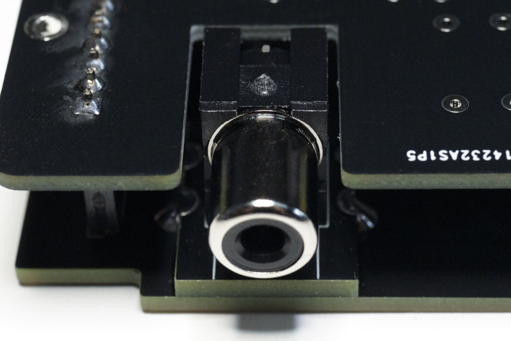
| RCA Jack soldered to the daughter-board |
 |
| RCA Jack soldered through the hole in the top-board |
Next solder the connector header to J1 on the top-board.
 |
| Connecter J1 soldered in position |
DO NOT SOLDER THE 20 PIN FEMALE HEADERS TO THE TOP-BOARD AT THIS TIME.
Main-Board
Start by soldering the resistors, then the diode (note polarity), then the ceramic capacitors, then the transistors and voltage regulator (again noting polarity), then the electrolytic capacitors (note polarity), then the inductor, then the switch.
Only once those parts are in place should you solder the headers. For now, the main-board requires the two 20-pin male headers, and two 4-pin (2 row) male headers. When soldering the 20-pin headers it is imperative that these are perfectly straight, and sitting at 90° (perpendicular) to the board. Do not allow the soldering iron to linger on any pin: the plastic will melt and you are at risk of losing or misaligning a pin.
Mating the Top and Main-Boards
Once those male headers have been soldered in, you are now in a position to mate the top and main-boards together.
 |
| Female 20-pin headers balanced on male 20-pin headers with top-board in position |
Balance the 20 pin female headers on top of the 20-pin male headers. DO NOT PUSH THEM TOGETHER YET. Now place the top-board onto the pins of the female header. This can be awkward getting all the pins from both headers through the corresponding holes (watch out for any slightly bent pins which may be preventing this). Once done, and ONLY when all pins from the female header are correctly through the holes in the top board, by applying even pressure across the top-board you should push the female headers vertically down onto the male headers - do NOT push at an angle or you risk bending the male pins. If you attempt to push the female headers onto the male pins without the support of the board you risk pushing some female contacts right out of the plastic. Ask me how I know.
 |
| Female 20-pin header pushed onto male 20-pin headers |
If you have followed the above instructions correctly, the male and female headers should now be joined at a good 90° angle and the RCA Jack on the top/daughter-board should slot neatly through the notch in the main-board (see picture below). This is why great care must be taken with alignment in the procedures above. Only now should you proceed to solder the female headers to the top-board. Once again, do not let the soldering iron linger on these pins: the plastic will melt.
Warning! When soldering the pins on the top-board I strongly advise you to mask off the gold borders with electrical or Kapton tape. You don't want a splash of solder to ruin the aesthetic.
Once done, the JaF Sandwich build is almost complete.
 |
| With top and main-Boards connected, RCA Jack should slot neatly through main-board notch |
Fixing to the 250466 SixtyClone Board
If installed in a case, the SixtyClone board will have to be removed as we need access to the bottom of the board. The JaF Sandwich is designed to be fixed to the 250466 SixtyClone board in 4 places: by both the modulator input and output headers, and by two 10mm standoffs which utilise existing mounting holes. This is extremely sturdy, and reversible, allowing the JaF Sandwich to be removed if necessary.
First you must solder the 4-pin single row male headers to both the input and output headers on the SixtyClone board, taking great care to ensure they are straight and as always do not let the soldering iron linger on the pins otherwise the plastic will melt.
 |
| Male 2.54mm Pin Headers on Input (to the right) and Output (to the left) positions of the 250466 SixtyClone M1 Modulator. |
Next, put the brass standoffs into the holes on the SixtyClone board. Note the type of standoffs being used, these have a thread at one end, and a screw hole at the other end. The threaded end should go through the SixtyClone board and this should be tightened with a brass nut. Do not fully tighten this yet. The standoffs should be able to move very slightly at this stage.

Make sure that the two halves of the JaF Sandwich are separate at this point. Using gentle pressure at each side, it is easy to slowly pry the two boards apart. For now you only need the main-board.
Now the 2 × 4-pin female headers need to be balanced on the 2 × 4-pin male headers on the SixtyClone board. Align the pins from the female headers through the holes in the JaF Sandwich main-board. When all the pins are through, apply gentle and even pressure to the main-board to push the female headers onto the male headers. DO NOT SOLDER THE FEMALE HEADERS YET.
Before doing anything else, we want to screw the main-board onto the two brass standoffs. DO NOT OVER-TIGHTEN THESE SCREWS. All being well this should be easy, the holes in the main-board should align with the screw holes in the standoffs. If they are a fraction out you may need to adjust the standoffs on the main-board (this is why we haven't soldered it yet) until the screws can be inserted and tightened. You may need to use plyers to prevent the standoffs turning as you tighten the screws. When the screws are tight, turn the SixtyClone board over and tighten the brass nuts on the standoffs. NB - over time it is likely these nuts will loosen, therefore you may wish to apply some Loctite to these threads.
Only now when the main-board is securely fastened to the SixtyClone on the standoffs, should you solder the 4 pin female headers. By following this process you are aligning everything and compensating for any slight deviations. This will prevent any solder joints from being stressed.
Now, unscrew the main-board from the SixtyClone and gently lift the main-board off the headers. Leave the brass standoffs attached to the SixtyClone. You can now screw the SixtyClone board back in the case.
When you are ready, and after applying the switch settings described below, you can place the JaF Sandwich back on the headers on the SixtyClone, ensuring the RCA Jack is positioned in the case hole before pushing it home. There are two notches in the top-board to allow a small screwdriver shaft to fit and screw the mainboard back onto the standoffs, though this is still quite awkward. It is easier to have the two screws already sitting in the holes in the main-board as you fit, that way you don't have to retrospectively lower them in. When reviewing the fit, the RCA Jack should be as close to central in the corresponding case hole as possible.
SWITCH SETTINGS
The switch can presently have 3 positions depending on what you are doing. Please note, switches 2 and 3 currently have no function and should remain off.
Position 1

For all normal use, i.e. when you simply want to output S-Video (Chroma and Luma) or Composite, the switch should be in the position shown above.
Position 2

If using the VIC-II-dizer passthrough, all switches should be OFF, as shown above. This isolates the LumaCode signal from some circuitry which would otherwise interfere. It is theoretically possible to use S-Video or Composite at the same time (if using two monitors for example) in which case switch 5 could be ON but I have never tested this as I have no requirement to.
Position 3

This position exists to allow experimentation with the VIC-II Kawari Mini - this is a modern replacement for the VIC-II chip in the C64 and has capabilities far beyond the original chip, including (with a prototype firmware), outputting LumaCode. This switch position allows this LumaCode signal from the Kawari to be passed through a voltage divider which must be isolated from the rest of the board, this is 100% essential. At the time of writing, this experimentation has been partially successful and the switch is retained for future experimentation. For further details and a link to a complete breakdown of this, please see bottom of page. When using the Kawari Mini in this manner, the LumaCode signal is using the circuits which would normally carry the Luma signal. Consequently, as there will be no Luma signal, it is not possible to use the S-Video or Composite circuitry (e.g. to use a second monitor) while using the Kawari Mini LumaCode and switch 5 must categorically be OFF, as shown above.
NORMAL OPERATION
In normal operation, the JaF Sandwich will pass Chroma, Luma/Sync and Composite video signals out of the standard C64 A/V Port. Chroma and Luma/Sync signals together form an "S-video" signal. Audio signals are generated in the SID Chip and passed directly to the A/V Port.
With the use of the correct cable, i.e. a cable which has been designed specifically for use with a Commodore 64 (either a Composite cable, or an "S-video" cable, or a cable which handles both) you can connect directly to a compatible monitor or TV. Or, for use with a modern TV, you can connect to a Composite or S-video to HDMI converter, which as the name implies, will convert the signals coming out of the C64 to a digital HDMI signal.
I would not recommend using the Composite video signal with a modern TV. You will find the quality of the video signal severely compromised with artefacts but I've retained this functionality for when there's no other option.
The S-video signal (Chroma and Luma/Sync) is the output I would recommend. The picture quality is the least compromised and very useable, though you will still notice some artefacts like jail bars (thin vertical lines regularly spaced across the screen) and color fringing (which makes some color combinations look smudged). However, for the most part, and in professionally produced demo's and games, you will barely notice.
Please view the video below, captured directly from my JaF Sandwich enabled 250466 SixtyClone via S-video using a 6569R5 VIC-II and converted to HDMI. The Demo used is Wonderland XII by Censor Design. There is no audio:
And here's the same demo, this time using the S-Video from the Kawari Mini for comparison:
VIC-II-DIZER PASSTHROUGH
This is not meant as a guide for The VIC-II-dizer. You should direct your interest to c0pperdragon's store and follow the extensive documentation linked from there. This guide assumes you have a VIC-II-dizer and the appropriate RGBtoHDMI decoder and that you know how to use that too.
The VIC-II-dizer comes with a two cable assembly. At one end is a small plug. At the other end are two crocodile clips. As per the instructions these crocodile clips are for use with an original RF Modulator.

The JaF Sandwich dispenses with this cable and requires a bespoke cable be created. For this you will require:
- 2× lengths of wire (colored to distinguish Ground and LumaCode)
- 2× Rectangular Connectors
- 4× Contact Crimps
Cut each wire to an appropriate length to fit between the pins on both the VIC-II-dizer and the connector header on the JaF Sandwich. Not too tight, and without too much slack. You could use the cable that came with the VIC-II-dizer - cut off the crocodile clips and go from there, or, you can do as I did and build a new cable from scratch. I used some very flexible, 26 AWG wire with silicon jacket (see BOM) which is perfect for this. I used black wire for Ground and White for LumaCode. I will refer to these colors below.
Crimp the contacts onto the ends of each wire then plug the contacts into the rectangular connectors.
Make sure the connector that is going to plug into the JaF Sandwich is the correct way round - the plug only fits one way!
Plug the other end into the VIC-II-dizer. Make sure that the white wire is definitely connected to the LumaCode output and double check this is connected to the LumaCode input on the JaF Sandwich. Do the same with the black GND (ground) wire. Check it again. And when you're sure they're connected correctly, check it again. Then use a multimeter to ensure continuity.
Finally, you can attach the RCA Plug from the RGBtoHDMI to the RCA Jack on the JaF Sandwich. The output connections are now all made and after following all necessary instructions for the RGBtoHDMI you will enjoy crystal clear HDMI video from your Commodore 64. Below is a sample of the video quality:
However...
The gotcha is there is no audio. This is the first of two major compromises with the RGBtoHDMI system and nothing to do with the JaF Sandwich. Now, maybe I'm just being a curmudgeonly old fart and your take may be very different, but to make a truly sensible, cohesive output from the C64, we can't neglect the audio. We really, really need someone smart to come along and enhance the RGBtoHDMI system with the ability to integrate audio. Until then, we need to employ either an external set of powered speakers to get audio from the regular C64 AV port, or add yet another external box to blend the audio with the HDMI video signal. Both of these solutions add considerably to the mess of wires I'm already contending with.
It may be that a new version of the RGBtoHDMI is on the horizon, incorporating audio (see here), but that would seem to be a ways off yet.
The second compromise (and again, this may not be an issue for you), is the lightweight nature of the RGBtoHDMI. At its best you can have the PCB and Raspberry Pi Zero in a 3D printed case. The combined weight is just 62 grams and is tethered to the C64 by a 20 inch RCA cable. This short-ish cable means it must sit beside/near the C64, which is also necessary to access the function buttons. However, if like me you have a hefty HDMI cable protruding from this dainty little box stretching off to a TV, it's not liable to stay on your desk for very long. Honestly, what this needs is a weighty aluminium or steel enclosure. Smaller is not better in this regard. Once again it all comes down to cost and the compromised nature of a small enterprise trying to keep prices down which is perfectly understandable.
EXPERIMENTING WITH LUMACODE FROM THE KAWARI MINI
As this function is only incidental to the JaF Sandwich, which is just acting as a pass-through with a simple voltage divider, it is not pertinent to outline the very lengthy process of "tuning in" the RGBtoHDMI and the Kawari Mini to output an HDMI video signal in this build guide. The full, excruciating, and almost successful process, is outlined here.
Connection wise, with the Kawari Mini installed in place of a VIC-II (and the experimental firmware both installed and correctly setup), simply make sure the JaF Sandwich Switch is in Position 3 (above) and off you go. On my 250466 SixtyClone no additional wiring is required as the LumaCode comes out of the Kawari Mini on pin 15, then is passed using the existing circuitry on the C64 (see image below) to pin 2 at the M1 modulator where it is picked up by the JaF Sandwich.

In practise, this process has all the downsides of the VIC-II-dizer and a whole bunch more, therefore it's not one I can hand-on-heart recommend: it's just too experimental. However, I did eventually get this to work and the video below is a capture demonstrating the video quality I'm getting.
REVISION HISTORY
Revision H: In Testing.
Headers joining top and main PCBs equally aligned with left and right PCB edges. Component layout efficiency drastically improved: will now only accommodate 1.78mm x 3.30mm resistors (e.g. RNMF Series by Stackpole Electronics Inc).
 |
| Revision H |
Revision G: Current.
Isolation jumpers removed and replaced with piano switch. Top board dimensions reduced to accomodate C64C Case design. Prototype production changed from PCBWay to JLCPCB.
 |
| Revision G |
_________________________
Revision F: Archived.
Cost reduced. Main PCB converted to 2 layers to reduce production costs. Daughter-board added to position RCA connector correctly. VIC-II-dizer header connectors replaced with a 2 pin single row connector. Voltage divider resistors added to accomodate LumaCode passthrough from Kawari Mini. Jumpers added to isolate Kawari Mini LumaCode when in use. Notch added to top board to accomodate C64C case clips.
 |
| Revision F |
__________________________
Revision E: Archived.
First dual PCB (sandwich) prototype. Headers added to join top and main PCBs. Cut out added to main board to accomodate RCA Connector. Component layout adjusted to accomodate less space on main, 4 layer, PCB. Top board introduced with RCA Connector and header connectors as passthrough for VIC-II-Dizer Lumacode.
 |
| Revision E |
_________________________
Revision D: Abandoned.
KiCad design only. This was a fork of Revision C where I experimented with the addition of a micro HDMI connector to allow passthrough from Large Kawari. Abandoned when it dawned on me this was a lot of hassle when I had no real interest in the Large Kawari and there was no way I could hand solder a micro HDMI connector to the PCB.
_________________________
Revision C: Archived.
Second and final single PCB design. Enlarged solder pads and traces. Improved component layout and fixed all operational problems with Revision B. 4 layer PCB.
 |
| Revision C |
_________________________
Revision B: Archived.
First Single PCB prototype. 4 layers.
 |
| Revision B |
_________________________
Revision A: Archived.
First "Janky as Fuck" (JaF) breadboard prototype.
 |
| Revision A |