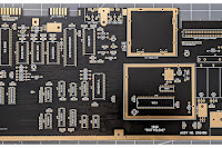
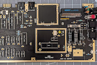
If you've read my series on how I built my SixtyClone Commodore 64, you will know my first build was a disaster, due entirely to the appalling quality of the chip sockets I bought. I initially wrote off that first build, stripping out some components and binned it. Then, after a change of heart, brought it out of the garbage and vowed to resurrect it to use as a test bed for future experiments.
Well, I'm delighted to report I have managed to find the time to resurrect that piece of crap PCB and it's now working. Working so well in fact that any animosity and annoyance I once held has evaporated and I've started to feel quite fond of it.
Because the sockets on that board continue to be dog-shit, I always knew it would be harder than it needed to be to bring it back to life and so it proved, but the first problem that needed attention was repairing the damage (or rather bypassing the damage) I inflicted by tearing (literally) the U1 CIA socket out of the board and bringing three traces along with it.
After cleaning this mess up, only the traces for pins 34, 35 and 36 of U1 were out of commission. Despite some other damage, there was enough copper left everywhere else to still make a good connection. Could have been a lot worse.
Next step was to find out where these broken traces went, and a quick scan of the schematic told me that 35 and 36 were address lines that simply went to pins 35 and 36 of the neighbouring CIA chip (U2). 34 is part of the reset line, and it looked like all I needed to do was connect this to pin 34 of U2. If this was correct, then it seemed I got really lucky and all I needed to do was connect a thin wire between pins 34, 35 and 36 of U1 to pins 34, 35 and 36 of U2. Hell even I could manage that without messing it up!
Next up was to obtain a whole new suite of chips. Nothing difficult here, just time consuming. And expensive.
I had to replace the three large capacitors, all the inductors and the voltage regulators which I'd salvaged for my new build.
For the large toroidal inductor at L4 I chose a 10μH, 4 amp, no-name variety I found on eBay as there was nothing sensible in stock at Digikey.
For the voltage regulators I decided to use the standard 7805 and 7812 components rather than the modern alternatives I used in my new build. My thinking here is I want, as far as I can, to have a board with standard parts that I can use to test and compare old components with, and against, modern replacements.
 |
| Puny heatsink. Seems to work though. |
The one exception to this is the PLA. The failure rate of the originals is such that there seemed no point throwing money away on a component that is practically guaranteed to fail so I stuck another PLAnkton EV in there.
Naturally, when everything was in place, switching on for the first time resulted in a black screen. Because of course it bloody did! Because the stupid sockets are all dog-shit. So now the challenge was to find which stupid dog-shit socket was giving me problems this time.
Luckily, I own a problematic dead test cart. No bevelled edge... WTF? Consequently, I don't like to use it but at the moment it's the only one I have so needs must.
I figured if this was the only socket that was giving me an issue for now, and it certainly seemed to be, I could solve this reasonably easily, and possibly permanently. What if I put a thin coat of solder on the legs of the IC? This would thicken the legs by a tiny fraction which might be just enough to make good contact with the dog-shit socket? If I could do this neatly it might be the perfect solution as it wouldn't stop me removing the chip at a later stage. So that's what I did, and it totally worked! Not only did this make the chip fit noticeably tighter in the socket, the PCB booted into dead test and ran perfectly. F**k you dog-shit sockets.
Removing the dead test my resurrected PCB booted to that lovely blue screen with... get this... a flashing cursor, which meant that my bodge repair to the ripped CIA traces had worked and as everything now seemed reasonably stable, presumably, my no-name toroidal inductor was working just fine too. Happy days!
_______________________________
Everything above was written in August 2022. It would take another 2½ years and a helluva lot more practice with a soldering iron before I felt confident enough, in November 2024, to finally and successfully desolder every single one of the awful sockets which plagued this machine. Even with the fixes I detailed above, I'd still get the occasional fault - a fault which was always resolved by massaging the chips back into their sockets. Desoldering, and replacing them all with Series 110 Mill-Max sockets has finally fixed everything, with not a single hiccup since undertaking the procedure.
_______________________________
So there we go. From broken crap to a working, reliable stunt machine perfect for testing. That's a result I'm well pleased with. Just one problem: no spare keyboard. Bugger.


