I am stoked to advise, to those brave souls who manage to read this far, that Revision C of my JaF64 solved all my issues and that this Modulator Replacement now works exactly as planned, with all the correct component values. The odd behaviour I was experiencing with Revision B is gone.
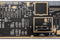
In the end I actually made a lot of changes: repositioning a bunch of components in the chroma circuit, widening the traces a lot, adding back capacitor C1, and bringing resistor R4 back to the specified value in the original schematic (180 ohms). I enlarged the solder pads and widened the holes. And what a difference. So much easier to solder together and plugging it in, it just works, and works really, really well. No messing.
Which specific change from Revision B fixed it? Either the re-addition of Capacitor C1 or changing the value of resistor R4. I haven't experimented either way yet so could be one, could be the other, could be both.
I've built two so far, one (pictured above) with all carbon 5% resistors, and another with metal 1% resistors (pictured below). There is no difference in the operation of the two. The build below also incorporates a shielded inductor at L2 (a Bournes 9250A-103-RC) This too makes no difference to the operation and is not worth the additional expense (I do prefer the look of it though).
Testing with both a 6569R3 and a 6569R5 there is a slight, but noticeable, difference in the color output which I assume is down to documented differences in luminosity values between these two VIC-II chips rather than anything to do with the JaF64. The R3 seems brighter and this observation is backed up by some research illustrated in this table derived from work originally undertaken by Marko Mäkelä.
As for video quality, well in side-by-side comparisons my JaF64 is on par with the mod I had been using (the S-Video Bypass/RF Replacement by Reinhard Grafl aka c0pperdragon,) and as such, the JaF64 now has permanent residence in both my 250466 SixtyClone boards. I can assure you, if the video output wasn't up to snuff I'd have no hesitation in calling it a day and abandoning this project. I'm basically seeing all the same artefacts (checkerboarding and jailbars) in both the c0pperdragon board, and the JaF64 and so I think we can safely assume this noise is a result of the signal coming from the VIC-II chip (or environs: checkerboarding I think from the Chroma, and jailbars probably from the Luma circuitry) and nothing to do with my design.
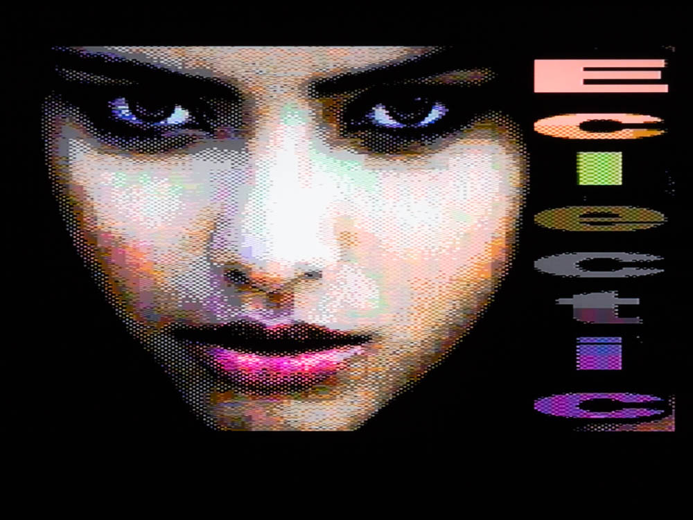
I'll conclude this final update with a selection of screen images taken with my DSLR. I found that at 15mm, a 1 second exposure at f29, ISO 100, moiré was eliminated, at the expense of some diffraction.
These images provide a "warts and all" overview of image quality and the artefacts I'm getting with my hardware.
Now this is important: different hardware will, I guarantee it, produce different results, so for absolute clarity this is the hardware I used in this instance:
- 250466 SixtyClone with 6569R5 VIC-II
- C64 S-Video/Audio lead - link to Ebay listing
- Tendak S-Video to HDMI Converter - link to Amazon UK
- A cheap and cheerful 5 meter HDMI cable
- A 2010 Samsung LE32C450E1W LCD TV
The S-Video signal here is being upscaled to 720p HDMI and the TV is set to output a 4:3 ratio image. Any lack of uniformity in color and vignetting apparent in these images is as an artefact of the DSLR/Lens and is not visible in the actual output. I encourage you to click on any of these for a larger view and zoom in to see the extent of the artefacts I refer to.
 |
| From Testbild-Generator V2.1 |
 |
| From Testbild-Generator V2.1 |
 |
| From Testbild-Generator V2.1 |
 |
| Black. No artefacts. |
 |
| White. No artefacts. |
 |
| Red. Bad jailbars. |
 |
| Cyan. Subtle jailbars. |
 |
| Violet. Bad jailbars. |
 |
| Green. Subtle jailbars. |
 |
| Blue. inconsistent checkerboarding. Sometimes subtle, sometimes bad. |
 |
| Yellow. No artefacts. |
 |
| Orange. Really bad jailbars. |
 |
| Brown. Really bad jailbars. |
 |
| Light Red. Bad jailbars. |
 |
| Grey 1. Bad jailbars. |
 |
| Grey 2. Bad jailbars. |
 |
| Light Green. No artefacts. |
 |
| Light Blue. Subtle jailbars. |
 |
| Grey 3. Subtle jailbars. |