|
| Rage Against the Machine |
The single biggest hurdle in this whole exercise can be summed up in one word: retrofitting.
If you read the first article in this series, you will be aware that this project is trying to add an RCA (also known as a Phono) Jack onto my JaF64 RF Modulator replacement for the Commodore 64. If you haven't read that article, then now you know.
My problem is positioning that jack accurately when so many variables are absolutely fixed:
- The Commodore 64 mainboard is a fixed height from the bottom of the case.
- Pin headers and stand offs are a fixed height on top of that. The pin headers I require don't come in a variety of sizes, it's 10.82mm high or nothing at all (either that or my Google-fu has failed me).
- And finally the hole in the C64C case that the jack needs to protrude from can't be moved and there's no way in hell I'm enlarging it (altering the case is the gravest of sins IMHO)
The lack of any flexibility here at all requires some alternative thinking to overcome. It boils down to this - how does one adjust the height of something when every one of its supporting elements are fixed?
This problem goes away if I remove the modular nature of the project. At the moment all these pin headers I'm moaning about allow me to remove and dismantle the JaF64 with the minimum of hassle. I could solder the JaF64 directly to the headers on the 250466, at a precise height and the problem vanishes, but then I lose the ability to just lift it off and that's unacceptable to me.
If I were designing the whole C64 from scratch, it wouldn't be a problem either. Available parts would dictate the outcome and the case hole and jack positioning would be positioned accordingly. But we're not. We're retrofitting. And we're retrofitting with parts that cannot be adjusted to accommodate the measurements we need.
So how bad is the problem? Well, there are two. One I didn't even factor into my thinking, because I'm stupid. and the other I anticipated, but miscalculated, again, because I'm stupid.
The first (and this is a doozy) is that my redesign will not actually fit. This is because of the plastic clips that help hold the C64C case together. One of these clips is sitting right where the JaF Sandwich needs to sit and it's large enough to prevent me from test fitting the new build.
 |
| C64C case clip prevents the JaF Sandwich from fitting |
The fact I never spotted this, or gave it any consideration at all is telling. Let that be a lesson to you kids. Anyway, in the picture above you can see the case clip extends the case approx 3mm into the area where the JaF Sandwich needs to sit. As a result, I can't mount the JaF Sandwich on its pins or standoffs and therefore can't determine precisely how badly aligned the RCA Jack (the barrel of which is the silver protrusion to the right of the case clip) is against the hole in the case. Sigh.
To solve this I could take the Dremel and carve out a notch but because I need to redesign the boards anyway (for reason's I'll outline below), I just need to go back into KiCad and create a notch:
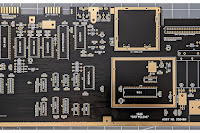
 |
| New Top Board design incorporating the "Pickle" Notch at top left |
I had initially thought that centre of the jack would be 0.9mm from the centre of the case hole. However, this was based on the fact that I thought the combined height of male pin headers connected to female pin headers was 10mm. It is not. It is nearer 10.82mm. Because of this miscalculation, the centre of the Jack will actually be near to 1.72mm from the centre of the hole. If you recall from my first article on this, I have 1.87mm wriggle room. So if everything is perfectly fitted, there will be only 0.15mm space to slide on the barrel of the RCA plug. In reality I think there will be a fraction more than that: The JaF Sandwich is mounted on two sets of pin headers 10.82mm high AND two brass standoffs which are 10mm high precisely. Given the offset nature and height discrepancy between the standoffs and the pin headers the JaF Sandwich is actually sitting at a very slight downward angle and fortunately it means the board is fractionally lower right where the RCA Jack is. We're only talking about 0.2mm but that might give me nearer 0.35mm wriggle room for the RCA Plug, but it might, just, fit.
Anyway, I've been having a good long think about what to do if the Plug doesn't quite fit and given the fixed nature of everything, the only thing I can think to do is create another PCB, a small daughter-board - thickness yet to be determined - which will sit between the top-board (pictured above) and the RCA Jack which will lower the Jack by the corresponding amount. This leads to more problems concerning how to mount this daughterboard - it can't sit on pin headers - it has to be mounted directly onto the top board and it has to carry the necessary signals but there are ways to deal with this (castellated holes). Because I don't want to do this unless it's absolutely necessary though, I'll only tackle it if I can be assured the RCA plug won't fit.
With all that explained, new boards have been designed, ordered, and now we wait again. Incidentally, to further reduce costs I've redesigned the old JaF64 (now the lower board of the JaF Sandwich) to have only two layers, not four. This means total production costs of two boards and shipping is down to just $16 which is awesome (if the new design works!)
One other thing which has happened since my first article is that Randy Rossi (developer of the VIC-II Kawari) has finalised his implementation of LumaCode generation (this applies to the mini board only - NOT the large board). Now, the way he describes how to get this LumaCode from the Kawari Mini, out to the RGBtoHDMI box is a real hack. See Randy's full description. But, reviewing his method, and giving this a good think, I came to the conclusion I could take the idea, and incorporate everything necessary into my JaF Sandwich.
Let me explain:
As Randy Points out, the first issue is that there is no VIC-II-dizer in this chain, thus we are missing a dedicated header for the LumaCode signal to be tapped into. Randy's method was to butcher a socket and create the necessary output pins (one for LumaCode, one for 5V and one for GND).
The second issue is that the raw LumaCode signal coming out of the Kawari Mini isn't quite to spec. In order to bring it closer to the required voltages, he has had to incorporate two Resistors (acting as a voltage divider) to bring it closer to something the RGBtoHDMI can recognize and decode. Randy demonstrates this by creating a web of wires and resistors hanging loose in the case, attached to his butchered socket and heading out of the case to the RGBtoHDMI.
Randy is only interested in seeing if this is theoretically possible, and he proved it is. He's not interested in making a final product incorporating the necessary pin headers in a future board revision which is fair enough but that does create an issue if I want to have a clean implementation. He has however, provided everything I need to design something that might work for me.
So, here's what I'm thinking:
- Randy has developed new firmware for the Kawari Mini which will generate LumaCode on the Luma Out pin. I'll install this.
- If I run this firmware, then without doing anything, that LumaCode will run from the Kawari's Luma Out pin, down the existing copper on the 250466 mainboard, all the way to one of the input pins (Pin 2) on my JaF Sandwich.
- So if I do nothing at all except run the firmware, I should be able to intercept the LumaCode on the JaF Sandwich. Graphic below highlights the path of the Luma line on the 250466 mainboard to illustrate all the circuits the Luma line is close to or crosses.

The only other thing I need to do is add some jumpers to make sure that this new circuit is completely isolated from the existing circuitry when we want to use it. That's not ideal but it's the best I can do to create an integrated design if Randy isn't proposing to integrate it formally into the Kawari Mini. So, with this in mind, this new circuitry has been incorporated into the new design I am waiting to be delivered from China.
The only issue I can foresee is letting the LumaCode use the existing circuit on the C64 mainboard, from the Kawari Mini, to the JaF Sandwich. I have a question mark over whether this trace is "clean" enough or will it let noise into the signal from all those nearby traces (see graphic above which highlights the path of the luma wire from source at pin 15 of the VIC-II socket, to end at pin 2 of the modulator header) which buggers it up. I guess we can only wait and see.
Finally, for this instalment; I have recently taken delivery of an RGBtoHDMI board and the necessary Raspberry Pi Zero to make it function. This article does NOT attempt to give ANY instruction on the use of this as that will need to be a whole blog by itself. However, be warned: The RGBtoHDMI project is a fucking minefield. There are several variants and the documentation is not for the faint-of-heart. The variant I got was from Copperdragon's Store which should definitely work with the VICIIdizer. However, for use with the Kawari Mini, I know from Randy's documentation that I will need access to a particular settings menu for "Analogue Interface Adjustments". The Analogue Interface is a third board normally used with a different variant of the RGBtoHDMI than the one I bought. Consequently, prior to taking delivery, I had no idea if I would be able to access this essential menu. C0pperdragon's Tindie page states "This board combines a basic RGBtoHDMI board with the features of the analogue add-on that are relevant for monochrome input." but doesn't explicitly state if the menu I need will function. As it turns out, the menu I need is available (see the Sampling Menu screen capture below) but it's completely different from the example Randy provided (link above). His menu would seem to be for RGB color, on my version it's for YUV. However, thinking this through I think in the RGB settings Randy demonstrated, Green (referred to as G) might be getting used for Luma, which is what the Y in YUV stands for. So if as a starting point I use:
- G Hi setting for my Y Hi
- G Lo setting for my Y Lo
- G Mid setting for my Y Mid
Plus if I use the same sync setting I might get somewhere. Who doesn't know what the fuck they're doing?
All that aside, at least, I'm in a position to test and check that the JaF Sandwich will at least function and pass a LumaCode signal from the VICIIdizer to the RGBtoHDMI which I can do on my SixtyClone test board. Or I would be if I hadn't forgotten to order a mini HDMI to HDMI cable. FFS. So I needed to order one of them and await delivery of that. Queue much throwing up of arms and utterance of despair and a great deal of rage suppression.
Luckily, this coincided with a booze fuelled time away with family so this enforced break gave me time to reflect, which was probably just as well because the complexity of this project was starting to get annoying and a pause was exactly what the doctor ordered. After this pause the cable arrived and I was ready to test.
 |
| The VICIIdizer with (heatsinked) VIC-II chip in my SixtyClone 250466 |
 |
| JaF Sandwich (prototype) view of Crocodile Clips from VICIIdizer |
 |
| Jaf Sandwich (prototype) view of RCA Output to RGBtoHDMI |
 |
| RGBtoHDMI in 3D printed case. Right LED is power, Left LED is Genlock. |
 |
| Screen Capture from RGBtoHDMI |
 |
| Screen Capture of Main Menu showing my basic settings. |
 |
| Screen Capture of Sampling Menu. Clearly for YUV. |
So, of my four initial criteria of what the JaF Sandwich needs to do, two are now met:


In the next installment I'll play around with the Kawari Mini and see if I can get that to talk to my RGBtoHDMI.