So, if you have absolutely no idea what I'm talking about, let's remedy that. Before proceeding though, please be aware this whole saga is stupidly convolted. And it's not all my fault.
Your first stop should be to C0pperdragon's store. There you will see a product called the "VICIIdizer". In brief, this is a PCB which sits between the C64 and the VIC-II chip. It listens to the communications between the two, and generates an output signal dubbed "LumaCode". So far so good.
 |
| C0pperdragon's VICIIdizer |
The relevant (and really clever bit) is how this LumaCode is fed out of the C64. Rather than requiring the user go through the arduous task of de-soldering the RF Modulator and install something else, the VICIIdizer comes with two cables terminated in crocodile clips. One of these simply clips to ground, and the other clips to the RCA Phono Jack, re-using this already-existing-but-until-now-defunct output. Simple.
(It's not really simple - it works like this: "rather than outputting an RGB or YUV signal which would require some sort of muti way connector or cable out of the computer, the board [the VICIIdizer] generates a four level mono video signal at two or three times the pixel rate of the original computer. Four levels means each pixel encodes 2 bits of information so for the C64 which has four bits per pixel, two mono pixels are required for each original c64 pixel." Quote from this Stardot forum.)
Outside of the C64, a cable then needs to be attached to the now reused RCA Jack and on to a box of tricks which can translate the LumaCode into an HDMI signal. This box of tricks is called "RGBtoHDMI" and is a hat (i.e. it plugs into) a Raspberry Pi Zero. The variant I'm using for now can be found at that link. This will output a pixel perfect HDMI signal on to your modern TV (without sound, but that's a whole separate issue).
Ok, so it's a whole new way of getting an HDMI signal out of the Commodore 64. And it's a way that greatly interests me. Even more interesting is that behind the scenes, the developer of the VIC-II Kawari, Randy Rossi, is examining and testing ways to try to incorporate the generation of LumaCode in the Kawari Mini (full conversation here and extensive instructions here) which dispenses with the need for the VICIIdizer board. Now, Randy was able to get this to work, but it is not easy and is nowhere near as simple as using a VICIIdizer with a regular VIC-II chip. For this to have any chance of working with my idea, I'll have to employ some thought. We'll pick up that part of the story in the next blog.
So, with all of that out-of-the-way, let's get to the point of this article:
Regular readers will be well aware that the Commodore 64 I use pretty much all the time is my SixtyClone, completely built by me, from almost all new parts. This did not come with an RF Modulator, instead, I designed my own: the JaF64 (which you can read all about over nine excruciatingly verbose parts). It never occurred to me then that the RCA Jack could have a modern use, so it was never incorporated into my new design.
To cut a long story right down to the meat and bones: I want to redesign my JaF64 to incorporate an RCA Jack for future use with the VIC-II-dizer (and, potentially, maybe, a LumaCode adapted Kawari). This means my redesign needs to do 4 different things:
- Accept the existing video input signals and output normal composite and S-Video signals as it currently does.
- Support a Lumacode signal from a VICIIdizer and output this through an RCA (phono) Jack. This will catagorically be a different approach from point 3.
- Support a Lumacode signal from the Kawari Mini and output this through an RCA (phono) Jack. This will catagorically be a different approach from point 2.
- Fit on the 250466 mainboard and C64C case without any modification.
Let's set a few points in stone from the outset:
- I am not going to change the way the JaF64 connects to the C64 motherboard. It's modular, it's rock solid. It's flippin perfect.
- The JaF64 will need a redesign to accommodate the planned changes but I'll limit this to essential changes only.
- The addition of the RCA Jack will be via a new PCB which plugs into the redesigned JaF64. And I'll explain why in some depth later
- No holes will be drilled in the case. Any changes must fit with the existing design.
- I will undertake this in stages only adding potential support for the Kawari Lumacode if I can get the VIC-II-dizer Lumacode working.
With that said, let me explain my thinking:
The first problem to overcome is adding an RCA (phono) Jack to my current design AND getting this jack to align with the existing hole in the case. If I can't do that, everything else is moot.
The existing hole in the case to accommodate the RCA Jack is 12mm in diameter. The jack itself is 8.3mm in diameter, thus if positioned correctly at the centre of the hole there should be a 1.87mm gap between the outside of the jack, and the inside of the hole all around. Therefore, we don't have a great deal of wriggle room to deal with misalignment.
Edit from the future. Some measurements below are incorrect. I assumed something because I'm an idiot. Specifically, I calculated everything on the assumption that the combined height of male and female pin headers was 10mm. It is not. All the headers I had, and I do have a variety, all had a combined height of 10.82mm which consequently, when my margin of error was already very small, threw everything off. I will have to deal with this in the future.
Theoretically, the top surface of the JaF64 sits 11.6mm above the mainboard. If an RCA Jack were simply mounted onto the JaF64, the centre line of the Jack would be a further 8mm higher than that - a total of 19.6mm above the mainboard. The original RF Modulator places the centre of the jack 12.7mm above the C64 mainboard. Thus we cannot simply mount the jack on the JaF64 as this would be 6.9mm too high.
By the use of standard pin headers however, it's easy to mount a new PCB 10mm above the JaF64. If we mount the RCA Jack onto the bottom of that new PCB, then I calculate the centre line of the Jack will only be 0.9mm from the centre line of the case hole. That might work.
What I am proposing then is to adjust the JaF64 to allow a new PCB be mounted on top. The new PCB will have the RCA Jack mounted to its base. This will drop to approximately the correct location for the hole. The JaF64 will have to have a hole cut in it to allow the RCA Jack to drop through. And the new PCB will have to have two holes cut in it wide enough to allow a Wera 2050 Micro Phillips PH 0x60mm screwdriver access to the mounting screws on the JaF64.
Don't worry if you can't picture any of that - digital renders are below. Meantime, here's a rough sketch of what I have in mind - nothing is to scale by-the-way, but the measurements shown are theoretically accurate.


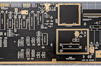
 |
| Top and bottom renders of the lower board of the JaF Sandwich |
 |
| Top and bottom renders of the upper board of the JaF Sandwich |
And finally a 3d rendering of the two halves to clearly demonstrate exactly what I'm trying to articulate. Hopefully you get the idea by now.