Please note: this article was published in June 2024. Since then, the RF Replacement V2 discussed here has become obsolete and unavailable. As of December 2024 it's been replaced by V3 (the ARRGH EFF OFF), therefore this post is now out-of-date.
It's finally here, the battle nobody's been waiting for: a head-to-head fight to the death between my JaF Sandwich RF Mod Replacement, and Mark (TheRetroChannel) Sawicki's Commodore 64 RF Replacement V2.
Wait, what the hell is this all about? Fear not, there's absolutely no axe grinding going on here: this is simply a personal interest review. I've heard great things about Mark's RF Modulator replacement for the Commodore 64 and obviously I have a great deal of interest in this area too as I built my own RF Mod replacement, the JaF Sandwich. Honestly, I'm just interested in seeing if Mark has managed to squeeze any last ounce of decent picture quality from it.
Please note: this article was written in June 2024 and references Version 2 of Mark's RF Replacement, not the Version 3 which was released later in that year and long after this was published.
Now obviously I'm the very last person on Earth who should be refereeing this particular fight. I'm more than a little bit biased after all. However, at the end of the day the single most important element is image quality and I'm perfectly able to put aside my partisan views and state one is better than the other. It should be an objective fact. Now I need to state at the outset, whilst I'm very interested in how good the image quality from Mark's RF Replacement is, regardless of the outcome, I'll be sticking with my JaF Sandwich. The simple reason for this is it's just not possible for the competition to be that much better. There is a limit, after all, to how good an analogue signal from a 40 year old computer can get and my JaF Sandwich is already very, very good and I'm really quite proud of it.
To allow you to see the same things I am, some of the images on this page are very large and may take a few moments to load on a less than stellar internet connection. Please be patient.
A Note About Picture Quality Testing
When it comes to testing picture quality, to ensure parity I will use both boards in my 250466 SixtyClone test board. I have two 250466 boards, one contains all new parts, the second, my test board, uses original MOS Integrated Circuits except for the SID and PLA which both died and have been replaced by a SwinSID Nano and a PLAnkton respectively. Please note, the use of a different C64 board assembly is likely to give different results to those illustrated here.
The VIC-II is a 6569R5. This is connected to my SixtyClone via a VIC-II-dizer which will NOT form part of these tests as both my JaF Sandwich and Mark's RF Replacement V2 boards simply act as a passthrough for the LumaCode that the VIC-II-dizer generates. Additionally, because I'm using an original VIC-II, this test will NOT benefit from the somewhat improved picture quality arising from use of the Kawari.
In each case I will use both a Composite and an S-Video cable attached to the 8-pin DIN socket on the SixtyClone. This will be passed to my upscaler which will then, in turn, pass an upscaled HDMI signal to my display. Where it is possible to do so, I will capture a few minutes of video and screengrabs from each board for side-by-side comparison (both connected to my HDMI upscaler and captured via an HDMI to USB card and OBS). For Mark's RF Replacement, I will compare the S-Video picture quality from both the onboard 4-pin mini-DIN and the 8-pin DIN on my SixtyClone, but I do not expect to see any difference.
With different hardware combinations: different VIC-II; different C64 board; different upscaler; different video capture: it is entirely likely, probable even, that different results would be observed, therefore it's important to note that in a similar test with your particular setup, you may very well come to a quite different conclusion than me.
Anyway, with the preamble out of the way, let's get ready to rumble!
Round 1. Price.
A single JaF Sandwich cost me around 26 GBP to make. Every component on the Bill of Materials can be sourced at one place: Digikey. However, because you have to order the minimum number of PCBs from your manufacturer of choice, you are kinda stuck ordering 5 at a minimum. If you're ordering 5 of each PCB you may as well build five JaF Sandwiches which is going to gouge you well over a hundred GBP. Good news is you have spares or you can sell some but that's extra hassle.
The C64 RF Replacement can be purchased as a self build and this would be the most cost effective route coming in at about 20 GBP each, shipped. The Bill of Materials recommends Mouser and AliExpress for the necessary components and the PCBs can be picked up at Mark's PCBWay Project page. However, Mark also sells these at his Lectronz store ready made but these are very expensive. Factor in shipping from Australia and one unit would cost me 71 USD or 58.79 GBP. However, although it costs way more, you don't have to invest time building the thing like you do with the JaF Sandwich. So in that regard, if you value your time (and you should!) costs start to get closer.
Digging through this, the self-build option for Mark's RF Replacement V2 is, self-evidently, the cheapest option and would thus win. However, bear in mind that with the JaF Sandwich I specified gold on my PCBs to match the gold on my SixtyClone. You could specify much cheaper options here and this would bring the prices much closer. But, you do require 3 PCBs (Top, Bottom and Daughter boards) to build the JaF Sandwich and even with the cheapest options that's still 2 more than Mark's RF Replacement.
Result: The RF Replacement V2 wins this round.
Round 2. Aesthetic Appeal.
Fully constructed JaF Sandwich on the left. RF Replacement V2 on the right.
If aesthetics weren't important nobody would bother beautifying their C64s. But they do, with PCBs in purple, blue, red, black to choose from (amongst others), matching capacitors and specially selected and colorful accessories such as the Ultimate II+ L in a rainbow selection of cases, and all sorts of other customisations. I cared enough about the JaF Sandwich to make it match my black SixtyClone board and please my aesthetic sensibilities, however, I acknowledge this is a personal thing and it might not please you.
The RF Replacement V2 on the other hand, does not satisfy me aesthetically at all. It looks spartan, functional and dare I say, rushed, to my eye: in the description at PCBWay Mark even admits it's "slightly less pretty". There's no rounded corners on the PCB itself and the silkscreen printing is a bit uninspired, though the Jay & Silent Bob reference gave me a smile. I'm merely critiquing the look of Mark's board and am in no way diminishing the hard work and research Mark put into his component choice, but I'm not scoring technical prowess in this round, that comes later. Of course, beauty is in the eye of the beholder. You may not even care: when the case is closed you won't even see it, but I definitely wouldn't be flexing with this on its looks alone.
Result: JaF Sandwich wins.
Round 3. Build and Installation.
So this should be an easy win for the RF Replacement V2. With the ready made option, if you're installing this properly, there's a bit of time required making sure the two connectors align with the case holes but once that's done and it's soldered in place, you're finished.
With the self-build option you have to source and solder all components to build the thing first, then install as above. Please note, the solder pads in Mark's board are tiny and whilst this doesn't prevent good soldering, it makes it a damn sight harder and he really should consider making them wider.
For my tests I will not be installing Mark's RF Replacement properly; I'm installing this temporarily in my test board and I want to be able to remove it with ease when I'm finished and because it will never be in a case I don't care about aligning jacks with case holes.
However, if you have installed it properly, it'll be a proper ball ache to remove it and if you ever want to swap another RF Mod replacement in future, you're going to be desoldering and hoping you don't lift pads. You could argue of course that once it's in you won't ever need to remove it but never say never.
Not so with the JaF Sandwich. Aside from the small matter of sourcing and soldering all the components yourself then dedicating a few hours of your life to building it (and that's definitely a no go if you're not confident with a soldering iron), once you have built it, it's designed to be modular: unscrew, lift out, drop in another.
There is no getting away from the need to solder something regardless of which RF Modulator replacement you happen to choose. That said, I'm giving this round to Mark's RF Replacement as the self-build route is less awkward to build than the JaF Sandwich and the ready-built version just needs installation. Additionally Mark's RF Replacement is stated to work in any C64 Longboard except ASSY 326298. The JaF Sandwich has never been tested in anything except a PAL 250466 SixtyClone so I can't say it has equal compatibility.
Result: As expected, this round is an easy win for Mark's RF Replacement V2
Round 4. Composite Picture Quality
This is where the battle heats up and the serious punches start to get thrown. I make no secret of the fact that I've never been impressed with the Composite picture quality from my JaF Sandwich and I am genuinely interested to see how much better the RF Replacement V2 can be. Remember, I'm not using a CRT so this test is determined by how these fair on my (relatively) modern, LCD display and capture equipment.
The first thing to say is that Mark's board works! That's a good start so at least it turned up for the fight.
The second thing to say is that the composite picture quality is crap. And this is exactly what I've been trying to say: no matter how improved your components, you cannot make a silk purse out of a sow's ear and the VIC-II's composite signal is about as porcine and aural as it's possible to get. On the positive side, it's very sharp and artefacts, whilst they are everywhere, in every combination, are not wildly out of control. It's useable, if you had no other choice.
The JaF Sandwich is similarly afflicted. As with Mark's RF Replacement, composite picture quality is crap, but crap in different ways. This is best exemplified in a few, close up screen captures. Please click the pictures below for a much larger view.
In the above example, which is quite representative, from the title screen of Commando, you can see ghosting in areas of high contrast is the worst problem with the JaF Sandwich whilst jailbars blight the RF Replacement V2.
And in this capture, with the RF Replacement color fringing is most apparent and where the white circle meets the white blocks you shouldn't be able to discern the edges of that circle. Again, in the JaF Sandwich, the ghosting is almost painful and it's suffering from the inability to merge the white circle and white blocks seamlessly too.
Interestingly, Mark's RF Replacement output is somewhat darker than the JaF Sandwich and that's regardless of the position of the variable resistor Mark incorporated into his design. I speak about this in the next round but in these tests the potentiometer is approximately half way. Black remains black and white remains white, but many of the other colors are distinctly different - something only obvious when directly comparing them. See the side-by-side comparison pictures below. Cyan is particularly weird, appearing too dark and green to my eyes. Yellow too looks to have too much green. I certainly didn't expect this difference, which must be down to subtly different voltage outputs arising from the particular components Mark has used on his board as everything else in the test is identical.
Whilst I prefer his slightly darker light grey (though maybe it's a trifle too dark?), I'm not a fan of that dirty cyan or light red. Please click the image below (and right click, to open in a new tab) to view this swatch at full size: all artefacts are then clear to see. The JaF Sandwich capture is always at the top left. The RF Replacement v2 is always bottom right.
Next up, video capture. This video plays through the Dreamtime 2023 demo by Profik. As with the swatch above, the JaF Sandwich capture is in the top left, the RF Replacement capture in the bottom right. I selected this particular demo for this test due to it's unique mix of graphics. Best watch in full screen at highest resolution to observe all artefacts.
When it comes to choosing a winner in this round, there really isn't one. Just take a good look at all those screen captures. Both are equally crap at Composite and where the RF Replacement might have the upper hand in one area (better separation of gray for example) the JaF Sandwich beats it in another (less prominent jailbars overall). Both are useable if you had no other choice, but if you're using a modern LCD monitor, you should definitely give yourself another choice. Scoring this was hard - should I score low because the image quality is so far from perfect? Or should I score high because they're both doing the best they can with a crap signal? In the end I scored low because, ideally, I'd liked to have seen some whizzy technical wizardry producing a cleaner signal.
Result: a low scoring draw.
Round 5. S-Video Picture Quality
Mark's RF Replacement has two S-Video options: the first is through the standard 8-pin DIN socket on my SixtyClone, and the second is through the dedicated 4-pin mini-DIN socket built onto his board. The obvious question is: does the signal through the 4-pin mini-DIN provide better video quality than the signal through the 8-pin DIN? As far as I can tell, electrically, the only difference on Mark's board is that the Color (aka Chroma) signal passes through a 120 ohm resistor on its way to the 4-pin mini-DIN. The signal to the 8-pin DIN does not. This makes sense: The raw chroma signal generated by the RF Mod is not to proper S-Video standards, it's too "hot", so this resistor brings that signal down to spec. It also assumes that if you're using the 8-pin DIN socket, the cable you're using for S-Video already incorporates that resistor. Mine does. So, theoretically, whichever socket you use, by the time the signal reaches your TV/Monitor or upscaler there should be no difference at all as both signals are the same.
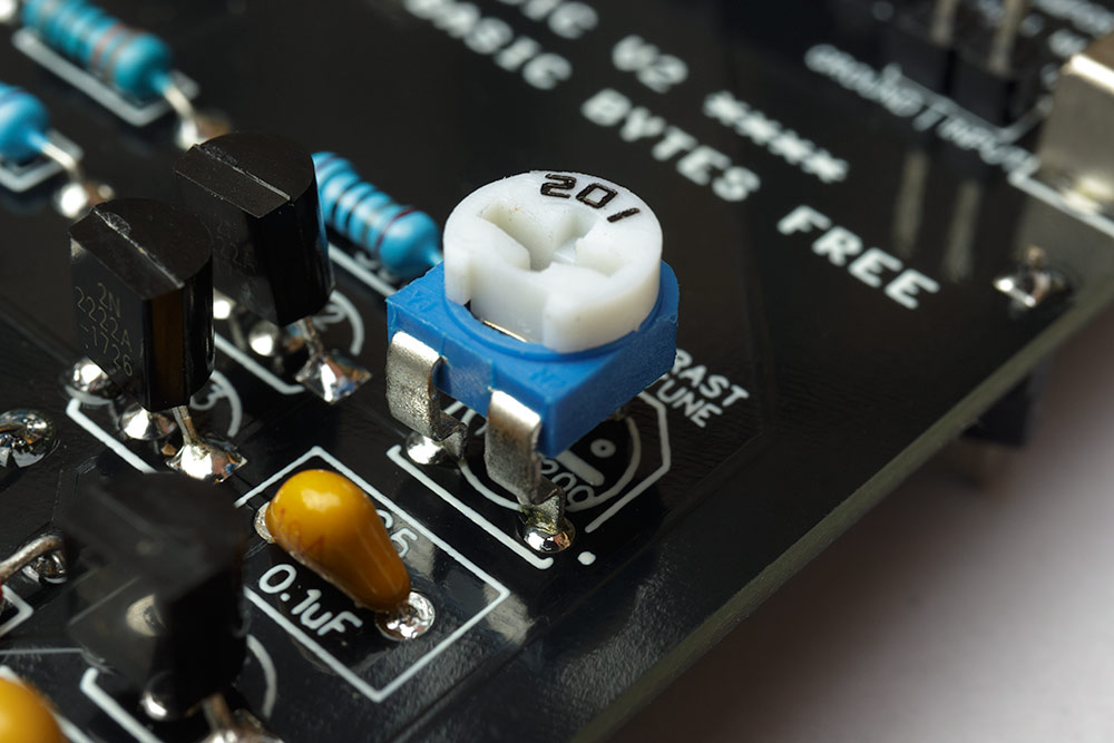
Additionally, in his design, Mark incorporates a 200 ohm variable resistor potentiometer to provide, and I quote: "Adjustable luma:sync ratio (contrast control)". Instructions for the correct use of this are in the Tindie store and so I slavishly follow them before doing anything else.
Macro of 200 ohm variable resistor potentiometer on the RF Replacement V2
Did this have any effect? Well, yes it did: with the potentiometer fully anti-clockwise there is less contrast, text is somewhat softer and this has the effect of disguising some jailbars; fully clockwise there is more contrast, text is sharper and the lack of softening means jailbars aren't as well disguised. The sweet spot, for me however is a fraction clockwise passed half-way which seems to be the best compromise between fractionally reducing jailbars and keeping things sharp. See the Luma schematic diagram below for an explanation of how this works. The image here illustrates the output observed with the commands POKE53281,1 and POKE53280,15 at the extreme ranges of the potentiometer:
Directly comparing image contrast at extremes of potentiometer range
Effect on text sharpness at extremes of potentiometer range
After this tinkering, I connect a normal S-Video cable to my HDMI upscaler and the 4-pin mini-DIN on Mark's RF Replacement and run the tests. Then I repeat the test with the S-Video signal from the 8-pin DIN using my trusty A/V S-Video cable bought from eBay.
I can say with cast-iron certainty there is not a scintilla of difference to picture quality by using the 4-pin mini-DIN on Mark's board, versus using the standard 8-pin DIN connector on my SixtyClone board, with my hardware. This was exactly what I expected. For that reason, and so I don't need to bother with an additional cable for audio, it's just easier and less hassle for me to use the 8-pin DIN as that combines everything I need in one cable. So from this point on I'm forgetting the 4-pin mini-DIN exists. However, what the use of the 4-pin mini DIN will allow is a standard S-Video cable of any length you like, if that's important to you. The 8-pin DIN S-Video cables don't have that flexibility as they're not mass produced so if length is important you'd need extension cables (both S-Video and RCA) but these are easy to obtain.
In the next part of the test I need to directly compare the S-Video quality from my JaF Sandwich. I run exactly the same test again, capturing video and screenshots so I can do side-by-side comparisons. This is the part of this whole exercise I'm really intrigued by as I honestly wonder just how good the video signal can be.
In truth, I'm seeing very similar things as with the Composite comparison, just with much improved clarity from both boards. Being as the differences I'm seeing must come down to the different components used, I thought it would be interesting to directly compare the components in the Luma and Chroma lines. If I've traced out Mark's board correctly, the schematic diagrams below should make the hardware differences very clear:
Luma schematics of the JaF Sandwich and RF Replacement V2
Luma Observation: in the original Commodore schematics (not pictured), it is specified that a fixed 470 ohm resistor be placed between the +5V line and the base of the transistor; this is what I did in the JaF Sandwich and this is what Mark has to say about that: "Added contrast control - something Commodore should have done.. Commodore used a fixed value resistor for all longboard RF modulators which doesn't take into account variances in the video output of each and every VIC-II. I've added this option so the output can be tailored for your VIC-II and display combination." Thus, in the RF Replacement V2, the variable resistor is placed in series with a fixed 390 ohm resistor. Assuming perfect component accuracy, this gives a configurable range of between 390 and 590 ohms between the +5V line and the base of the transistor. Putting the variable resistor approximately half-way as I have done in these tests gives a series resistance of approximately 490 ohms which is close to the value originally specified and which I felt gave the best picture with my hardware. I really like the ability to configure this and am sorely tempted to replicate (i.e. straight out steal) this idea for a future iteration of the JaF Sandwich, sorry Mark!
What is absolutely baffling to me however, is what I see when I put the oscilloscope on the luma line. Because this made no sense, I've quadruple checked but comparing oscilloscope readings from both boards really does give the exact opposite result of what I would have expected. While taking these readings the C64 is outputting a black border and 5 columns of equal size in black, dark gray, mid gray, light gray and white respectively:
Gray bands capture. JaF Sandwich (Top) and RF Replacement V2 (bottom)
Coupling = DC
Trigger = rising edge
Time = 10µs/DIV
Voltage = 200mV/DIV
Yellow Line is the JaF Sandwich
Blue Line is the RF Replacement V2
In each case you can clearly see the stepped values expected from black to white and 3 shades of gray, the higher the value, the lighter the shade. Peak to peak values in both boards are almost identical coming in at a fraction over 1 volt.
Counterintuitively, Mark's board, the blue line, clearly has distinctly higher values for the 5 shades, which in my simple mind should mean they appear lighter on screen, but in reality the exact opposite is true, especially apparent with light gray which in Mark's board is much darker on screen. I guess this must have something to do with the differing voltage range between the black point and white point (680mV in Mark's board versus 750mV (approx) in the JaF Sandwich) which is the only other obvious overall difference, but honestly, I just don't have the smarts to explain what I'm seeing on the oscilloscope versus what I see on the TV. Electronics is bloody hard. If anyone can explain this to me in language a 5 year old would understand, please get in touch coz it's driving me nuts.
Chroma schematics of the JaF Sandwich and RF Replacement V2
Chroma Observation: despite having a near identical layout, component values are quite different. For the JaF Sandwich I've used component values as specified in original Commodore documentation. Mark has departed from that. This, once again, is where my background knowledge breaks down, and I cannot explain why (e.g. I know what transistors do, but I don't understand how they change a signal, nor am I able to calculate how different transistors might deal with the same signal). Regardless, the hardware differences you see here result in different chroma output when everything else is identical. This is important to know, as when it comes to using, for example, the VIC-II Kawari, which allows you to adjust hue, brightness and saturation: if you were to use the built in values (which for PAL were actually conceived by Mark) then different RF Modulator replacements will output different results. I can reliably say then that there is no such thing as universal standard values for the Kawari.
Moving on from hardware differences, by viewing the full size graphics below you'll see the full gamut of artefacts. As far as artefacts are concerned there's little to choose between the boards. With the exception of the differing shades, in this side-by-side comparison both boards show virtually identical artefacts. The RF Replacement is slightly cleaner in the greys, but that cyan still doesn't look right to me. The JaF Sandwich's red is the least messy of the two. To view at full size, click the image below, then right click, and open in a new tab.
Looking at some stills, I can start to see more interesting differences. The image below, from the Wonderland XIII demo by Censor Design starts to get quite revealing:
Now looking very closely at the hand on the left, near the knuckle of the middle finger:
Notice the much more defined 'cross-hatching' effect seen in the RF Replacement, which is almost invisible in the JaF Sandwich - it is there but you need to strain to see it. As far as I can tell, all the color in this cross-hatching is light red, which we established in the swatch above is darker in the RF Replacement. The light red is perfectly visible in both images as it comes down the middle finger, but the cross-hatch effect at the knuckle is barely visible in the JaF Sandwich. The RF Replacement's darker palette in an image like this provides additional contrast and makes the image appear sharper (look at the specular highlight on the ball in the 1st image which is punchier in the RF Replacement), whereas in the JaF Sandwich, less contrast means the colors appear to blend giving a smoother look. This is another really interesting difference.
Again, as with the composite comparison, I've captured the S-Video output of both boards while running the the Dreamtime 2023 demo by Profik. The differences between both boards this time are more pronounced and the graphic weaknesses are fully on display here. Once again, to observe all artefacts, it's best to watch this in full screen at the highest resolution.
Neither of these boards is outputting a bad S-Video picture. In-fact, both are doing a really good job and whilst I think it's only fair to give this round to Mark's RF Replacement for the better contrast and sharper image my wee JaF Sandwich really held its own and I'm perfectly satisfied it's doing almost as well as the "best".
Result: RF Replacement V2 wins this round.
Round 6. Audio and other stuff.
Well, this is kinda easy. My JaF Sandwich ignores audio completely. The input audio header goes nowhere and does nothing. I've no interest in playing with dual SIDs to obtain true stereo and so I made no provision for it. Having said that, I have thought about it after-the-fact and had it been an option for me, I would have liked to accommodate stereo audio even though I'd never use it but the unfortunate positioning of the risers I've used means that case hole is blocked. Now that riser position could be changed, but then I'm left trying to find a suitable 3.5mm connector with enough reach to be accessible via that case hole, and as far as I can see, no such connector exists. Sacrilegious as it is to admit, I'm not a chip-tune fan (my musical tastes don't extend past rock/metal and the SID chip doesn't lend itself to these genres) and I've always been happy to stick with the dual mono I get through the normal 8-pin DIN and my chosen S-Video A/V cable, so this doesn't bother me, but it most definitely might bother you.
Mark's RF Replacement goes all out however, adding a dedicated and configurable 3.5mm socket. This can be configured via a switch to output dual mono, or composite video and mono audio, or an external connection where one channel carries mono audio and the other carries, for example, LumaCode from the VIC-II-dizer connected to the nearby pin headers, or audio from a second SID for stereo.
Configuration switch for 3.5mm connector on the RF Replacement V2
As stated, I've no interest in stereo audio, but I am very interested in LumaCode and I very much like that this is an option. One would require a 3.5mm to RCA splitter cable to utilize this and connect to the RGBtoHDMI, but that's easy to obtain and whilst I'm not going to test this option (it's just a passthrough and there is no reason at all it wont work perfectly) I appreciate the addition. I note however that this mixed use of one connector means if you want to use LumaCode and stereo audio, you are out of luck.
With any new RF Replacement today, there is a need to accommodate some means of getting LumaCode out. I firmly believe this is the future for perfect video from the Commodore 64. The inability, however, of the RGBtoHDMI design to embed audio into the HDMI signal, and the subsequent requirement for external powered speakers or an additional audio embedder is a real inconvenience. My JaF Sandwich, with its RCA (Phono) connector specifically for LumaCode connects directly to the RGBtoHDMI cable, so there's no requirement for a splitter. However, Mark's solution does output audio on the same cable, albeit mono. I require access to the audio from the 8-pin DIN via a second cable so that's more clutter but I will get dual-mono. In both cases that audio signal will have to go to powered speakers or an HDMI Audio Embedder which is yet more clutter, and expense. The perfect solution is for a future iteration of the RGBtoHDMI which deals with audio and video. That's the dream, and it's being looked at but it may be a ways off yet.
My current assembly of the JaF Sandwich can also deal with experimental LumaCode from the VIC-II Kawari Mini. Mark's board can't. (Please see here for how I managed this). And whilst that will forever remain experimental (with the current generation of the Kawari Mini boards at any rate) and used by, well, almost nobody ever, it's a proven principle.
This brings us to HDMI from the large Kawari board. Mark does provide a different variation of his board which incorporates an HDMI passthrough which is a very elegant solution to getting HDMI out of the C64 case but that is not something I'm interested in here, and it's not the board I bought. For my purposes (note: 'my purposes' - these are not the same as your purposes and so you must draw your own conclusions) all of the extras Mark provides on the board I did buy are inconsequential and provide no additional benefits.
All of that said, I will give the win in this round to Mark and only because his board will accommodate stereo for dual SID users. That's a real world benefit Mark's board deals with nicely that I ignored, and, due to riser positions on the current JaF Sandwich design blocking the case hole, I cannot accommodate.
Result: RF Replacement V2 wins this round and subsequently the fight.
Post Fight Analysis.
So the fight is over and there have been no knockout blows, but we do have a winner on points. Mark's RF Replacement V2 is the better board: it may not be pretty but it's cheaper, it's easier to build and it offers a tangible extra the JaF Sandwich can't. All of that is nice, but what really counts is the video quality. Both do the best they can with composite but it's not a recommended option. S-Video is where both boards shine and the RF Replacement is sharper with better, and adjustable, contrast. I do wonder however, if I hadn't been actively looking and directly comparing for the purposes of this article, whether I would ever have noticed as there's not much in it. I suspect the difference in luminosity of the light gray would have been the biggest and most obvious giveaway. As it is, I doff my cap to you Mr Sawicki, that's a damn fine bit of gear you've got there; congrats!
Despite being the also-ran, I'm really proud of how my JaF Sandwich fared in this. I've seen with my own eyes that it can really hold its own and that my efforts haven't been a waste of time. I find myself even happier with it than I was before and conclude that the best of the competition so far, isn't ahead by much at all.