If you've been following along then you will know that over the previous instalments I have taken you on the bumpy ride of designing and building a brand new RF Modulator replacement (The JAF64) for my 250466 SixtyClone board with no real clue what I'm doing, just to see if I could, and for the LOLs... though to be fair there has been far more cursing than LOLing.
Here, in Phase 2, Part 3 and the penultimate entry of this saga, I finally take delivery of the PCB design I have poured over for weeks. For clarity it was on the 2nd of May 2022 I first had the idea to do this, and the 20th June 2022 I received the manufactured PCBs. 50 days. In that time I've got to grips with the schematic, built a working prototype on a breadboard, learned the basics of using KiCad and managed to successfully submit Gerber files to have the PCB built. I'm certainly not unhappy with this timescale.
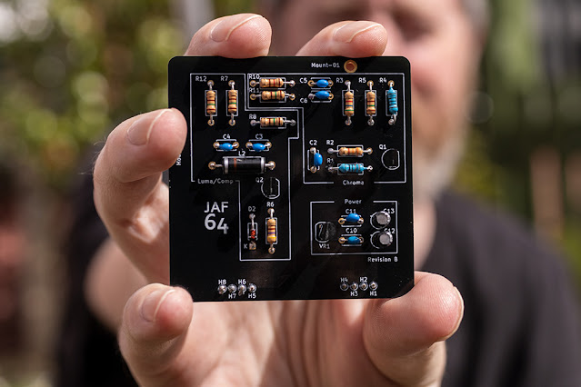
I spent the morning of 21st June 2022 soldering the components into the first PCB and learned several valuable lessons to take forward to a future Revision C:
- The solder pads were really very small making soldering something of a chore. I will be enlarging these in any future revision.
- The 3 solder pads of the Voltage Regulator and Transistors were awfully close together making soldering them without bridging anything a pain.
- The holes in the solder pads for the component legs could stand to be enlarged just a smidge to aid flow of solder through the board.
However, demanding as it was, I managed to solder it all together over a few hours without issue.
 |
| Yeah, I get outside sometimes |
And now, finally, I get to plug it in to my SixtyClone for the first time and turn it on:
 |
| Video Out - ignore the moiré - that's not present in actual output |
I had a picture, but it was devoid of color. Monochrome. Achromatic. Black and white. Oh FFS.
Obviously, this meant my Chroma circuit wasn't working and I puzzled over this for hours.
- I double checked all my solder joints. The multimeter gave me correct continuity everywhere.
- I double checked my components to ensure I hadn't accidentally soldered the wrong components in the wrong places. Everything was correct.
This meant that it was nothing obvious. I started to wonder if maybe a component was faulty and so with the board plugged in to the SixtyClone and with everything powered up I started just poking at different parts on the Chroma circuit to see if anything changed on screen and believe it or not, eventually this paid off.
I had this idea to piggyback a resistor on to the resistors in the board, and by that I mean I just hand-held a known working resistor and touched the legs of that against the legs of the resistors in circuit, just to see if anything happened. When I got to R1, like magic, the screen lit up with sweet, sweet color.
Of course I assumed that R1 (a 1K resistor) was toast and I'd probably burned it up by overheating while soldering so I replaced it and tried again:
Same f*****g problem. What the hell? Once again I bridged it with a known working resistor and once again the color came back. WTF?
Piggybacking resistors like this does not sum the total resistor value. Instead theres a calculation, so if I piggybacked a 1K resistor on top of another 1K resistor the calculation is:
1/((1/1000)+(1/1000)) = 500 ohms
so whatever else I was doing, I was definitely reducing the ohms in the circuit by doing this.
To cut a VERY long story short, here's what I eventually found out by experimenting and swapping out resistors in R1:
- 100 Ohm resistor gave me color
- 320 Ohm resistor gave me color
- 500 Ohm (piggybacking) gave me color
- 1k Ohm resistor gave me black and white
- 2k Ohm resistor gave me black and white
So. Despite working in my breadboard just fine, a 1K resistor in my PCB at R1 caused the whole Chroma circuit to fail? I only had 100 and 320 Ohm resistors to hand, piggybacking the original 1K resistor with another 1K resistor gave me 500 Ohms so am missing any tests between 500 and 1K but I gotta admit, because this all worked in the breadboard, with the same components, I just don't understand this at all. The Janky As F**k 64 certainly continues to live up to its name.
I've left the 320 Ohm resistor in place for now and although a concern, I'm not so worried about any effect this may have on the VIC-II chip. R1 is directly connected to pin 14 of the VIC-II chip but changing this particular resistor to a lower value simply allows more signal to go to ground (more details below) so I can't see that having an adverse effect on the VIC chip directly. But any future tests will have to be done on another board as the poor solder pads at R1 have now been subjected to 5 resistor replacements and are in a terrible state. However, everything does now work, and despite my concerns, it works very, very well on both Composite and S-Video.
 |
| An image of the Composite video output |
I want to be absolutely honest and avoid hyperbole:
The Good
Colors are very nicely saturated though subtly inaccurate (probably due to changed resistor values). There is minimal color bleed and jailbars, though still present, are as minimised as I've ever seen them. S-video output is more pleasingly saturated than Composite output but the latter is still nice.
All the static noise I noticed while testing the breadboard prototype is gone.
My measurements appear to have been millimetre perfect as my PCB fits and bolts on to the SixtyClone precisely (pictures below).
No components get hot. Only the Voltage Regulator gets warm to touch, but only warm, never so hot I can't grip it with my fingers comfortably.
The Bad
If I'm being particularly critical, the picture is definitely soft via composite and I suspect this is playing some part in minimising jailbars. In s-video it's perfectly sharp and consequently jailbars are definitely more apparent. I do wonder what effects I'm seeing from the reduced impedance at R1, the missing capacitor C1, and the reduced impedance at R4? Only further experimentation will tell.
The Ugly
The fact I don't know what's going on with R1 and the implications of changing it is somewhat concerning.
Summing Up
 |
| The working JAF64 PCB mounted on the 250466 SixtyClone |
 |
| 10mm M2 standoffs aligning perfectly and holding the JAF64 securely in place |
 |
| The JAF64 (Revision B) in its completed glory |
Although I've still got a lot of experimenting to do, this seems like a good time to reflect on what I've achieved so far.
Despite having high hopes from the outset, I never dreamt I would actually be able to see this through to completion. I fully expected at each stage to hit an insurmountable roadblock so to be holding a kinda-working PCB in my hand is something I'm mighty proud of.
I have obviously learned a lot along the way, but there are still massive gaps in my knowledge and my fundamental ignorance of basic electronics has, without doubt, made things much harder. Instead of making educated decisions I'm guessing and stabbing in the dark which is a long way from ideal. For this reason it's pretty obvious I've got to this stage by pure luck. However, without doing something like this, I'd learn nothing and at the very least I now know what I don't know.
If I have one gripe however, it's that pretty much all of the online explanations I could find for more complex things, like how transistors work for example, are utterly impenetrable for a novice (once you get passed the basics) and believe me, I've tried: VCE, IEQ (amongst a plethora of other things)? Nope, not even the faintest whiff of a clue what they mean, why they're important, how to apply them or how to calculate them. A common theme is the reader should already have a certain level of knowledge and if you don't? Well tough titty, and that's a shame. I have no idea where to even start learning that stuff.
What is the future for this project?
I've already started to make changes to the design based on my soldering experience (enlarging the solder pads) and I've made some minor changes to the trace routing to eliminate vias and add capacitor C1 back in (see below). I will widen the traces and I want to make the whole circuit more efficient so will cut some trace lengths by shuffling a few components around but overall, because the existing design is, as far as I can see, noise and interference free, I'm not minded to make radical changes.
Obviously I need to get to the bottom of the concerning R1 resistor issue and this will require a great deal of digging, which I've started in earnest: I now know R1 provides the base of the transistor with a reference to ground, and I know that the lower the value of R1, the lower the impedance of the chroma signal to ground. In other words: higher resistance (e.g. 1K Ohms) allows less signal to ground, forces more signal to the transistor and thus increases gain - thats high impedance. Lower resistance (e.g. 360 Ohms) allows more signal to ground and less signal to the transistor, lowering gain. Thats low impedance. Oh and now I also know that when using the word "impedance" we are referring to resistance but on Alternating Current, so the Chroma and Luma signals coming out of the VIC-II are AC, not DC. Even that wasn't obvious to me, coz I've never studied electronics, but when you realise that, it becomes clear why the capacitors in the chroma line are important, to filter out unwanted DC signal (see below about Capacitor C1).
However, none of this tells me why lowering the impedance, which is what I've done, makes my circuit work in the PCB but is not required in the breadboard with identical components. I've clearly messed something up but I'm not seeing it yet.
Whether all that is related to the picture softness and slightly inaccurate color output remains to be seen. Neither of these issues are that bad (I am being particularly critical for complete honesty) and so I want to undertake some burn in tests and just run the thing for hours to test robustness.
I've also discovered that removing capacitor C1 was a mistake. If you cast your mind back to Phase 1, Part 5 I removed this from the chroma circuit at the same time as I removed inductor L1. Together these components created a band pass filter to remove both high and low frequencies from the chroma signal but it seems capacitor C1 is still required to ensure only the AC (Alternating Current) part of the chroma signal is amplified by the transistor (coz this is an amplifier that we're building here) as it impedes the low frequency DC element. As such C1, acting as a high pass filter, will categorically make its way back into a future Revision C and I do wonder if its removal, and the consequent increase in unwanted DC to the transistor base is why I've had to reduce the impedance? That kinda makes sense but I keep coming back to "it freakin works on the breadboard!" Who knew capacitors did so much? Not me that's for sure.
In other words, I'll keep plugging away at my design and try to comprehensively answer the questions and concerns still hanging over it. I will eventually write an update when I've resolved all this. [Edit: It's resolved and that write up is here]
I'm definitely within spitting distance of achieving what I set out to do and designing a working modulator from scratch. For me, that's pretty damn epic.
Please note, it's not my intention to make this design publicly available yet. I couldn't, in good conscience, release a design I don't fully understand, and as there are already plenty of well thought out and effective alternatives out there, if you are in need of an RF Modulator replacement I would politely direct you to them.
If I manage to resolve the issues and concerns outlined above I may consider releasing as a Shared Project on PCBWay though in all honesty I truly see no need: this was always a personal project simply for learning, the fun of it, and the satisfaction of actually making something from scratch.
Costing Up
Creating this PCB wasn't free of course, and I like to keep a record of my spending, both as a personal reference and to give others an idea of exactly the sort of investment they are looking at when embarking on these types of projects. Bear in mind these costs are only accurate now (June 2022) and will become less indicative as time moves on. I also ordered way more components than I needed for a single build so I could experiment - that pushes the cost up too. Future revisions will only add to this. All that said, below are the full details of my spending for this project now. All costs include delivery where applicable, and do not include items I already had (solder, Dupont wires etc) but which were still necessary for the project.
TOTAL PROJECT COST:
R&D Costs
£4.99 - 9v Battery Snap Connectors (Amazon)
£9.99 - 3 x Breadboards (Amazon)
£21.25 - 4 x Transistors (Ebay - a total rip off)
£43.39 - Revision A Components (Digikey)
£31.55 - Revision B Components - Voltage Regulator etc (Digikey)
£2.58 - 20 x Resistors (Ebay)
£113.75 - Subtotal
Manufacturing Costs
£75.23 - Revision B PCB Manufacturing (PCBWay)
Total Cost
£188.98 GBP (€220.04 EUR, $231.94 USD)
I also invested a great deal of time over the 50 day development period. My best guess to that is approximately 100 hours including learning KiCad, creating all the graphics and writing up this blog. I think this was time and money well spent to fulfil this particular ambition, but I understand if many don't agree - one can, literally, go and buy an excellent C64 Modulator replacement for less than £15. For me, that wasn't the point and I really do have a tremendous sense of achievement about the whole experience. That's no bad thing. That's no bad thing at all.


