Thursday, 22 December 2022

Making Video for a Commodore 64

The Commodore 64, is many things, but a media centre is not one of them. That said, there is a mighty fanbase for "chiptunes", and if music generated by the SID chip in the C64 is your bag, then there are thousands of hours worth of music to enjoy. Video though, is a whole different ball game. There are pretty insurmountable hardware limitations that mean the C64 can never be a multi-media powerhouse. Or can it?

Well no. Obviously it can't. But. We can take a decent stab at generating recognizable video, which we can play back on a suitably equipped C64. With certain limitations.

What do I mean by "suitably equipped"? Well in its native state the C64 has no chance of playing video of more than a few seconds. There simply isn't enough RAM. We will need to add an REU (RAM expansion unit).

Back in the day these were huge, and expensive, coming in 3 flavours: 128k, 256k and 512k. And whilst they significantly improved on the native 64k in the computer, even they are not suitable for what I'm doing today. No, this is very much a 21st century update and would A) simply not have been possible in the 1980s and B) Requires a fairly modern PC to implement.

So, the first thing we need is a huge (comparatively) REU. In the Ultimate 2+ cartridge, Gideon Zweijtzer, has incorporated a 16MB REU. That is hardware that exists, and can be used (my own will be with me early in 2023 I hope). The Turbo Chamelion 64 will also do this. There is talk of others producing REUs of a similar size but for the moment I'm not aware of anything else currently available that will do the job and so, for now, I am sadly restricted to emulating as I have no suitable hardware.

Luckily, VICE will emulate a 16MB REU so I will be working with this.

The next step, and by far the most complex, is converting some video to a format which will fit into the REU, and which the C64 is capable of playing. We are not going to be able to play modern MP4 files for example, that's for damn sure.

So how is this accomplished? Well, it's certainly not without it's frustrations, but once again, if I can do it, anyone can. Now I did not invent this process, good grief no! This process comes to us courtesy of Daniel Kottmair (aka daddlerTL) over at Forum64.de. When I first read about it I was very keen to have a go. I followed daddlerTL's instructions and used his software which can be obtained here, but I did have to adapt them to my particular circumstances. I will explain as I go.

WHAT FOLLOWS IS SIMPLY A SUMMARY OF THE STEPS I UNDERTOOK. FOR DADDLERTL'S OFFICIAL INSTRUCTIONS PLEASE REFER TO THE LINK ABOVE.

We first need a suitable video. We are going to be seriously restricted in video length so a 2 hr feature film is out of the question. Ideal candidates are adverts, short music videos, a short clip from a film, or perhaps a short video you film yourself.

Depending on the final frame rate you decide to use, your video length can be a max of 5 mins 47 secs (at 5 frames per second (FPS) in a 4:3 ratio) or as short as 1 min 38 seconds (at 16.67 FPS in a 16:10 ratio).

I decided to use a short clip from the 2000 film High Fidelity for my initial experiment. The specific clip I had in mind is 49 seconds long and is in 16:9 format. The instructions tell me that at 16:67 FPS I can have as much as 1 min 46 seconds so this clip is ideal for a first try. It's a brief, self contained soliloquy and so will work as a stand alone piece, and will not cut out in the middle of an action sequence for example which is something that must be considered.

On my Windows computer, I need to get my movie clip, which is in MP4 format, into a piece of software called Virtual Dub. Virtual Dub does not recognise the MP4 format. The instructions states it recognises AVI files however, none of the AVI files I generated were acceptable to the software either. This is probably user error but, anyway, I worked around it:

My video editing software, Davinci Resolve, CAN export individual frames of a movie as TIFF files. Now Virtual Dub doesn't recognise them either (coz of course it doesn't) but it does recognize JPEGs and BMPs which naturally, Davinci Resolve CAN'T export. FFS.

So. Using Davinci Resolve, I edit the whole movie down to just the 49 second clip I want, I resized my export to 320 x 184 pixels and exported 1500 (approx) TIFF files to a folder. Still in Resolve, I then exported the audio track as an MP3 file.

Next I need to convert all 1500 TIFF files to JPEGs. Fortunately I have Adobe Photoshop, and luckily, it can do a batch convert so it only took 10 minutes or so for Photoshop to do its thing.

I then used Audacity to convert my MP3 soundtrack file to an 8 bit WAV file (at 11700 Hz). I also increased the volume here as I felt the track was particularly quiet.

And now I can finally import the 1500 JPEGs to Virtual Dub where I need to resize according to the instructions and adjust my frame rate from the original (25 FPS) - which I had to manually set as it defaulted to 10 FPS because I imported image files, not a video file - to the new 16.67 FPS. Then I can export my converted frames (Virtual Dub exports BMP files) which numbered 840 for my clip.

Needless to say, this all takes time.

I now have 840 BMP files which now need converted into the colors and pixel alignment that the C64 can understand. For this I need another piece of software called Project One.

What needs to happen in Project One is that you import a single frame of your video that is representative of the whole clip. In other words it should contain the color palette and objects/people that you want. With this frame I basically messed about with all the settings and sliders until the example output looked as good as it possibly could, when directly compared with the original. Remember, the C64 only has 16 colors to play with and you can't have all of them in the 8x8 blocks which make up the C64 video output where its limited to 2 colors per block, so this is basically a damage limitation exercise and very much a matter of taste. I decided to use random dithering as well.

When you have an output you're happy with, you don't want to be repeating that process manually for every frame! So, instead the instructions tell us to run a script, which is just a macro, that will automate the process for you, opening each frame, converting it according to the settings you've just made, save it, then move to the next frame until all are completed. For 840 frames this took about 1.5 hrs. This is the most painful part and your PC is pretty much out-of-action while this runs.

So, from an initial MP4 file, I now have 1500 TIFFS, 1500 JPEGS, 840 BMPs, 840 KLAs, an MP3 and a WAV. Good Grief.

Anyway, I now have a folder of 840 KLA files. Into this I move my WAV soundtrack file and a copy of the last piece of conversion software I will be using: "KoalaVideo REU Maker" which is in daddlerTL's download (link above).

Running this I see it's a command line program where you simply answer a number of prompts about your files - ratio, framerate etc and it just goes about its business blending all our image files and soundtrack into one REU file (I actually made two REU files - one for each type of SID).

To check it worked I enabled the REU in VICE (Done via Settings) and loaded one of my newly created REU files in. I then ran a program specifically designed to play the video and soundtrack back called "Koala Video Player" (included in the download daddlerTL put together at the link above). I recorded the result from VICE for your viewing pleasure:


All in all I'm very happy that I now have a process nailed down, and as a puzzle to solve I had a blast (obvious irritations aside). However, something is nagging me.

As a technical exercise, this is wonderful. I really, really like it and am thoroughly impressed that this is even possible on 40 year old hardware, albeit with enhancement. However. The only reason to do this is for fun. It's not really practical.

All those hoops to jump through to watch a video in poor quality when I can just watch it on my modern laptop? I am forcing the C64 to do something it was never designed for and which, without modern intervention, it could never do. The same could be said of all the other modern stuff I've appended to my C64 (pi1541, WIC64) but these simply enhance or replace stuff the C64 was capable of AND add value. Is anyone making "exclusive" content in this format that make it a must-have? And if so why? It's easier to just use YouTube for distribution.

Other than the initial wow factor, this brings nothing of real value to my C64 experience and indeed, requires very expensive hardware to accomplish. I wouldn't want to watch an entire movie in this format (even if that were possible) and producing it in the first place is a series of backward steps in which we incrementally degrade the video a little bit more, so I'm definitely not sold on this.

However, if techniques like this were to be employed by demos and games, to enhance the experience, I'd be prepared to change my mind. Then again, as stated, playing with these old computers is all about having fun, otherwise what's the point? And there is no denying there is something strangely delightful about the idea of watching shit quality video on a Commodore 64. 


Wednesday, 26 October 2022

A brand new C64 Cartridge Guide? Probably not.

Not content with managing to design and have manufactured a perfectly respectable RF Modulator replacement for my SixtyClone 250466 Commodore 64, I had another itch to scratch.

I keep thinking about my "all new" philosophy of these clone boards and whilst I have had to hit the second hand market for a keyboard, CIA chips, the 6510 CPU and the VIC-II there are much smarter enthusiasts than me working hard to resolve this. These are not simple things and it takes a very special range of skills to attempt to replicate these. Skills which I will never, ever achieve. However, buying these parts in the second hand market really does fill me with guilt. I truly don't want a new build to mean an old one has to be butchered. 

What I found strange though, is that there is one very particular part that is simply not available new. That part is the humble Cartridge Guide:

An original Cartridge Guide obtained from Retroleum


Now, I am not saying no one has replicated these before: I know of two: a version has been created for the Ultimate64 board by Gideon Zweijtzer and another, slightly altered design for the C64 Reloaded MK II by Jens Schönfeld. However these are not for sale separately, and besides that, appear to be bespoke to the specific design of those boards and would not fit a SixtyClone which is designed to accept an original Cartridge Guide.

To my, albeit uneducated, eyes, this particular part is simply a stamped and bent piece of metal. By employing highly specialised techniques (ok - I stuck a magnet on it) I've established it is magnetic and it is somewhat flexible. A tour of the internet will reveal pictures of these in all manner of  conditions, including rusted, so this evidence suggests these are made from a type of mild steel. It cannot be beyond the wit of our species to have these remanufactured, I thought. However, despite extensive searches on the interwebs, I have drawn a blank. No one is selling them.

So, still on a high from my stunning triumph with my JaF64 RF Modulator replacement I figured I would give this a bash. I mean, how hard could it be, right?

So what would it actually take to construct a new Cartridge Guide?

  1. Accurate measurements of the original part.
  2. Some CAD software.
  3. A manufacturer.

As part of the build process for my SixtyClone, I bought an original cartridge guide but as yet I have not soldered this in to place. Thus it was available to me to measure up.

When I had the PCB for my JaF64 manufactured, I used PCBWay. As well as printing circuit boards it did not escape my attention that PCBWay also offer Sheet Metal fabrication:


Though I must upload a design before I can get a quote so I have zero idea what sort of costs we might be looking at, at these initial stages. And no, this isn't an advert for PCBWay - this is simply the only company I know of that offers the service I need for low volume production. I only require 1 part.

So, of the 3 requirements listed above, we do at least have 2 of these available. All that remains is the CAD software to turn the measurements I need to take, into a file that can be uploaded. That means more Googling.

Now, it will come as no surprise what-so-ever to anyone reading this that I have no experience with CAD software. In the past I've messed about with Bryce and Blender which are more like modelling tools than proper CAD software (maybe I'm doing them a disservice but that's my abiding impression) so I was on the hunt for something which was both free to use, but comprehensive.

As it was, my two requirements (comprehensive, free to use) pretty much narrowed down my search to a single option. FreeCAD. So one substantial download later I was losing myself in the menus and icons of something which was about as far from intuitive as I've ever seen.

Queue hours and hours of YouTube trying to figure out how to get started. I do find (and it was exactly the same when I was designing my PCB) that it really helps to have a specific project in mind when it comes to learning new software as it helps to focus my experimenting and learning, and so it proved here. But I'm getting ahead of myself. Before all of that, the first thing I did was purchase a Digital Vernier Caliper:


And with this, set about the original cartridge guide to get all the necessary measurements. I should say tolerances aren't so tight that we need to be accurate to 100ths of a millimetre so this much cheapness caliper should suffice.

So far so easy. However, when it came to the next stage, using FreeCAD... Well, this is a process I loathed and I confess to hating this software with a passion. It just doesn't seem to be able to do what I need it to do and no matter how much research I do, I've got so far and am now kinda stuck.

Let me explain:

The Cartridge Guide is just a 1mm thick piece of steel with six 90 degree (approx) bends to create the shape we are all familiar with. On each side there are 2 prongs, one of which is an L shape to allow it to "lock" into the main PCB. Curious to the design are 4 embossed "ribs" (for want of a better word), stamped into the steel: one on each side and two on the top. These "ribs" - probably more accurately referred to as "beads" - were (it seemed to me) the whole point of the Cartridge Guide: they protrude into the space around the Cartridge Connector on the main PCB just enough so that ham-fisted attempts to insert a cartridge would be "guided" into the correct position by physically preventing you from moving the cartridge too far out of position, whilst still providing "wiggle room" to allow for easy insertion/extraction. Wiggle room you would not have if the whole guide was simply smaller and a tighter fit. The more I think about it, the more I realise just how smart this design this is.

Underside of Guide showing bends, solder legs and embossed ribs

The image below gives an indication of the tolerances available around an original Commodore 64 cartridge within the Cartridge Guide, mounted on my SixtyClone 250466 PCB:

View of an original Cartridge Guide surrounding a cartridge

Getting the calipers around the guide revealed the beads only protrude about a millimetre into this space leaving about 1.5mm between the edge of a cartridge and the guide on the horizontal and about 3mm between the top of a cartridge and the guide on the vertical. The beads can't possibly be there for strengthening the steel as they're in the wrong direction for that so the only possible reason for their existence is to help guide the cartridge into the socket. As such they should be replicated.

With FreeCAD I was, with relative ease, able to design the flat shape of the cartridge guide and the solder legs. Here's a much zoomed in screenshot of the right L shaped solder leg for example:


What I couldn't do in FreeCAD, at least natively (and I find this jaw dropping) was bend my flat shape.

After some more Googling and YouTube watching I discovered a plugin called "Sheet Metal" which was able to bend my shape, but in a way I did not expect - if I want to put a right angle in a flat design with a length of 50mm, and the radius of the bend I insert is 1mm - the new bend adds 2mm to my overall length (1mm on the horizontal and 1mm on the vertical) which has the effect of making the design both too tall and too wide. Sigh.

Anyway, after fighting with all this for a while I was able to create the basic design I was looking for but honestly, it was way harder than it really needed to be.

FreeCAD's 3D View of the correctly shaped Cartridge Guide

And yes, whilst there's still some work to do to refine the shape of the L shaped prongs, this is still, in essence, what we are looking for. But can you see what it doesn't have?

That's right, there's no beads. And these aren't there because FreeCAD can't do it (at least not in any way I can fathom). I'm clearly under a misapprehension here: isn't sheet metal design a really basic element of CAD? Isn't beading and bending steel a critical element of any sheet metal design? How is it possible that this CAD software either can't do it or obfuscates the process so much that it's not recorded anywhere I can find? Obviously this is my ignorance but honestly, it's been an annoying and frustrating chore.

So, this is as far as I've been able to get. Without the beads it would be a poor replica so there is no point in trying to have anything manufactured. But to satisfy my curiosity, I can export a .step file of what I do have and upload that to PCBWay to get a preliminary quote on what it would cost if I were able to finish the design...


Holy shit. $48. For one part. That includes a black powder-coat, but does not include shipping. And as you can see, that is a pre-quote - the official quote can only be obtained after an engineer review, and let's face it, that price isn't going down, is it? There is also no guarantee PCBWay could, in fact, stamp the part with the ribs, even if I was able to build them into the design - that would require a bespoke die which would probably be extortionate.

I think it's now obvious why this hasn't been done before. Nobody in their right mind is going to pay the best part of $50 (not including shipping which at a guess would be around $30) for a new part when there is plenty of salvage available for a couple of pounds: retroleum, for example sells them for £2.50 (when in stock).

So this particular hair brained scheme is on hold for the foreseeable (probably permanently to be fair). Don't get me wrong - I would absolutely be dumb enough to pay that money, once, to get a bespoke part for my SixtyClone, but until the design is fully resolved, if at all, my bank balance is safe. I can say I tried, but with my limited skills it doesn't seem feasible, or even remotely cost effective.


Sunday, 14 August 2022

Resurrecting my busted SixtyClone C64.

If you've read my series on how I built my SixtyClone Commodore 64, you will know my first build was a disaster, due entirely to the appalling quality of the chip sockets I bought. I initially wrote off that first build, stripping out some components and binned it. Then, after a change of heart, brought it out of the garbage and vowed to resurrect it to use as a test bed for future experiments.

Well, I'm delighted to report I have managed to find the time to resurrect that piece of crap PCB and it's now working. Working so well in fact that any animosity and annoyance I once held has evaporated and I've started to feel quite fond of it.

Because the sockets on that board continue to be dog-shit, I always knew it would be harder than it needed to be to bring it back to life and so it proved, but the first problem that needed attention was repairing the damage (or rather bypassing the damage) I inflicted by tearing (literally) the U1 CIA socket out of the board and bringing three traces along with it.


After cleaning this mess up, only the traces for pins 34, 35 and 36 of U1 were out of commission. Despite some other damage, there was enough copper left everywhere else to still make a good connection. Could have been a lot worse.

Next step was to find out where these broken traces went, and a quick scan of the schematic told me that 35 and 36 were address lines that simply went to pins 35 and 36 of the neighbouring CIA chip (U2). 34 is part of the reset line, and it looked like all I needed to do was connect this to pin 34 of U2. If this was correct, then it seemed I got really lucky and all I needed to do was connect a thin wire between pins 34, 35 and 36 of U1 to pins 34, 35 and 36 of U2. Hell even I could manage that without messing it up!


Next up was to obtain a whole new suite of chips. Nothing difficult here, just time consuming. And expensive. 

I had to replace the three large capacitors, all the inductors and the voltage regulators which I'd salvaged for my new build.

For the large toroidal inductor at L4 I chose a 10μH, 4 amp, no-name variety I found on eBay as there was nothing sensible in stock at Digikey.


For the voltage regulators I decided to use the standard 7805 and 7812 components rather than the modern alternatives I used in my new build. My thinking here is I want, as far as I can, to have a board with standard parts that I can use to test and compare old components with, and against, modern replacements.

Puny heatsink. Seems to work though.

The one exception to this is the PLA. The failure rate of the originals is such that there seemed no point throwing money away on a component that is practically guaranteed to fail so I stuck another PLAnkton EV in there.

Naturally, when everything was in place, switching on for the first time resulted in a black screen. Because of course it bloody did! Because the stupid sockets are all dog-shit. So now the challenge was to find which stupid dog-shit socket was giving me problems this time.

Luckily, I own a problematic dead test cart. No bevelled edge... WTF? Consequently, I don't like to use it but at the moment it's the only one I have so needs must.


Inserting gave me one white flash. This pointed to the RAM chips (specifically U9) and whilst this was only indicative it seemed like a reasonable place to look first. I reseated both chips and noticed the chip in U10 was much looser in the socket than U9. On a hunch I pressed very firmly on the chip in U10 with my finger and in this position, pushing it down hard, I switched on the computer with the dead test cart again. And sure enough it sprang to life and just started running. The minute I removed my finger, everything crashed: that's pretty definitive.

I figured if this was the only socket that was giving me an issue for now, and it certainly seemed to be, I could solve this reasonably easily, and possibly permanently. What if I put a thin coat of solder on the legs of the IC? This would thicken the legs by a tiny fraction which might be just enough to make good contact with the dog-shit socket? If I could do this neatly it might be the perfect solution as it wouldn't stop me removing the chip at a later stage. So that's what I did, and it totally worked! Not only did this make the chip fit noticeably tighter in the socket, the PCB booted into dead test and ran perfectly. F**k you dog-shit sockets.

Removing the dead test my resurrected PCB booted to that lovely blue screen with... get this... a flashing cursor, which meant that my bodge repair to the ripped CIA traces had worked and as everything now seemed reasonably stable, presumably, my no-name toroidal inductor was working just fine too. Happy days!

_______________________________


Everything above was written in August 2022. It would take another 2½ years and a helluva lot more practice with a soldering iron before I felt confident enough, in November 2024, to finally and successfully desolder every single one of the awful sockets which plagued this machine. Even with the fixes I detailed above, I'd still get the occasional fault - a fault which was always resolved by massaging the chips back into their sockets. Desoldering, and replacing them all with Series 110 Mill-Max sockets has finally fixed everything, with not a single hiccup since undertaking the procedure.

_______________________________


So there we go. From broken crap to a working, reliable stunt machine perfect for testing. That's a result I'm well pleased with. Just one problem: no spare keyboard. Bugger.


JaF64 Final Update

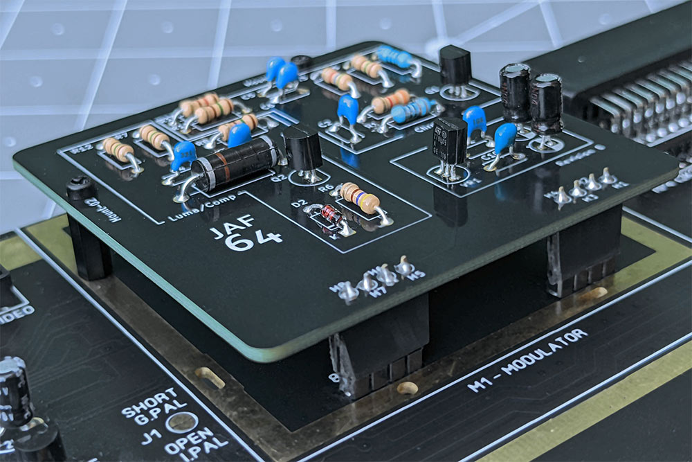
I am stoked to advise, to those brave souls who manage to read this far, that Revision C of my JaF64 solved all my issues and that this Modulator Replacement now works exactly as planned, with all the correct component values. The odd behaviour I was experiencing with Revision B is gone.


In the end I actually made a lot of changes: repositioning a bunch of components in the chroma circuit, widening the traces a lot, adding back capacitor C1, and bringing resistor R4 back to the specified value in the original schematic (180 ohms). I enlarged the solder pads and widened the holes. And what a difference. So much easier to solder together and plugging it in, it just works, and works really, really well. No messing.

Which specific change from Revision B fixed it? Either the re-addition of Capacitor C1 or changing the value of resistor R4. I haven't experimented either way yet so could be one, could be the other, could be both.

I've built two so far, one (pictured above) with all carbon 5% resistors, and another with metal 1% resistors (pictured below). There is no difference in the operation of the two. The build below also incorporates a shielded inductor at L2 (a Bournes 9250A-103-RC) This too makes no difference to the operation and is not worth the additional expense (I do prefer the look of it though).


Testing with both a 6569R3 and a 6569R5 there is a slight, but noticeable, difference in the color output which I assume is down to documented differences in luminosity values between these two VIC-II chips rather than anything to do with the JaF64. The R3 seems brighter and this observation is backed up by some research illustrated in this table derived from work originally undertaken by Marko Mäkelä.

As for video quality, well in side-by-side comparisons my JaF64 is on par with the mod I had been using (the S-Video Bypass/RF Replacement by Reinhard Grafl aka c0pperdragon,) and as such, the JaF64 now has permanent residence in both my 250466 SixtyClone boards. I can assure you, if the video output wasn't up to snuff I'd have no hesitation in calling it a day and abandoning this project. I'm basically seeing all the same artefacts (checkerboarding and jailbars) in both the c0pperdragon board, and the JaF64 and so I think we can safely assume this noise is a result of the signal coming from the VIC-II chip (or environs: checkerboarding I think from the Chroma, and jailbars probably from the Luma circuitry) and nothing to do with my design.

I'll conclude this final update with a selection of screen images taken with my DSLR. I found that at 15mm, a 1 second exposure at f29, ISO 100, moiré was eliminated, at the expense of some diffraction.

These images provide a "warts and all" overview of image quality and the artefacts I'm getting with my hardware.

Now this is important: different hardware will, I guarantee it, produce different results, so for absolute clarity this is the hardware I used in this instance:

  • 250466 SixtyClone with 6569R5 VIC-II
  • C64 S-Video/Audio lead - link to Ebay listing
  • Tendak S-Video to HDMI Converter - link to Amazon UK
  • A cheap and cheerful 5 meter HDMI cable
  • A 2010 Samsung LE32C450E1W LCD TV

The S-Video signal here is being upscaled to 720p HDMI and the TV is set to output a 4:3 ratio image. Any lack of uniformity in color and vignetting apparent in these images is as an artefact of the DSLR/Lens and is not visible in the actual output. I encourage you to click on any of these for a larger view and zoom in to see the extent of the artefacts I refer to.

From Testbild-Generator V2.1

From Testbild-Generator V2.1

From Testbild-Generator V2.1


Black. No artefacts.

White. No artefacts.

Red. Bad jailbars.

Cyan. Subtle jailbars.

Violet. Bad jailbars.

Green. Subtle jailbars.

Blue. inconsistent checkerboarding. Sometimes subtle, sometimes bad.

Yellow. No artefacts.

Orange. Really bad jailbars.

Brown. Really bad jailbars.

Light Red. Bad jailbars.

Grey 1. Bad jailbars.

Grey 2. Bad jailbars.

Light Green. No artefacts.

Light Blue. Subtle jailbars.

Grey 3. Subtle jailbars.


Thursday, 23 June 2022

Designing a C64 RF Modulator Replacement Phase 2, Part 3

If you've been following along then you will know that over the previous instalments I have taken you on the bumpy ride of designing and building a brand new RF Modulator replacement (The JAF64) for my 250466 SixtyClone board with no real clue what I'm doing, just to see if I could, and for the LOLs... though to be fair there has been far more cursing than LOLing.

Here, in Phase 2, Part 3 and the penultimate entry of this saga, I finally take delivery of the PCB design I have poured over for weeks. For clarity it was on the 2nd of May 2022 I first had the idea to do this, and the 20th June 2022 I received the manufactured PCBs. 50 days. In that time I've got to grips with the schematic, built a working prototype on a breadboard, learned the basics of using KiCad and managed to successfully submit Gerber files to have the PCB built. I'm certainly not unhappy with this timescale.


I spent the morning of 21st June 2022 soldering the components into the first PCB and learned several valuable lessons to take forward to a future Revision C:

  1. The solder pads were really very small making soldering something of a chore. I will be enlarging these in any future revision.
  2. The 3 solder pads of the Voltage Regulator and Transistors were awfully close together making soldering them without bridging anything a pain.
  3. The holes in the solder pads for the component legs could stand to be enlarged just a smidge to aid flow of solder through the board.

However, demanding as it was, I managed to solder it all together over a few hours without issue.

Me and my JAF64
Yeah, I get outside sometimes


And now, finally, I get to plug it in to my SixtyClone for the first time and turn it on:

Video Out - ignore the moiré - that's not present in actual output


I had a picture, but it was devoid of color. Monochrome. Achromatic. Black and white. Oh FFS.

Obviously, this meant my Chroma circuit wasn't working and I puzzled over this for hours.

  1. I double checked all my solder joints. The multimeter gave me correct continuity everywhere.
  2. I double checked my components to ensure I hadn't accidentally soldered the wrong components in the wrong places. Everything was correct.

This meant that it was nothing obvious. I started to wonder if maybe a component was faulty and so with the board plugged in to the SixtyClone and with everything powered up I started just poking at different parts on the Chroma circuit to see if anything changed on screen and believe it or not, eventually this paid off.

I had this idea to piggyback a resistor on to the resistors in the board, and by that I mean I just hand-held a known working resistor and touched the legs of that against the legs of the resistors in circuit, just to see if anything happened. When I got to R1, like magic, the screen lit up with sweet, sweet color.

Of course I assumed that R1 (a 1K resistor) was toast and I'd probably burned it up by overheating while soldering so I replaced it and tried again:


Same f*****g problem. What the hell? Once again I bridged it with a known working resistor and once again the color came back. WTF?

Piggybacking resistors like this does not sum the total resistor value. Instead theres a calculation, so if I piggybacked a 1K resistor on top of another 1K resistor the calculation is:

1/((1/1000)+(1/1000)) = 500 ohms

so whatever else I was doing, I was definitely reducing the ohms in the circuit by doing this.

To cut a VERY long story short, here's what I eventually found out by experimenting and swapping out resistors in R1:

  • 100 Ohm resistor gave me color
  • 320 Ohm resistor gave me color
  • 500 Ohm (piggybacking) gave me color
  • 1k Ohm resistor gave me black and white
  • 2k Ohm resistor gave me black and white

So. Despite working in my breadboard just fine, a 1K resistor in my PCB at R1 caused the whole Chroma circuit to fail? I only had 100 and 320 Ohm resistors to hand, piggybacking the original 1K resistor with another 1K resistor gave me 500 Ohms so am missing any tests between 500 and 1K but I gotta admit, because this all worked in the breadboard, with the same components, I just don't understand this at all. The Janky As F**k 64 certainly continues to live up to its name.


I've left the 320 Ohm resistor in place for now and although a concern, I'm not so worried about any effect this may have on the VIC-II chip. R1 is directly connected to pin 14 of the VIC-II chip but changing this particular resistor to a lower value simply allows more signal to go to ground (more details below) so I can't see that having an adverse effect on the VIC chip directly. But any future tests will have to be done on another board as the poor solder pads at R1 have now been subjected to 5 resistor replacements and are in a terrible state. However, everything does now work, and despite my concerns, it works very, very well on both Composite and S-Video.


An image of the Composite video output

I want to be absolutely honest and avoid hyperbole:

The Good

Colors are very nicely saturated though subtly inaccurate (probably due to changed resistor values). There is minimal color bleed and jailbars, though still present, are as minimised as I've ever seen them. S-video output is more pleasingly saturated than Composite output but the latter is still nice.

All the static noise I noticed while testing the breadboard prototype is gone.

My measurements appear to have been millimetre perfect as my PCB fits and bolts on to the SixtyClone precisely (pictures below).

No components get hot. Only the Voltage Regulator gets warm to touch, but only warm, never so hot I can't grip it with my fingers comfortably.

The Bad

If I'm being particularly critical, the picture is definitely soft via composite and I suspect this is playing some part in minimising jailbars. In s-video it's perfectly sharp and consequently jailbars are definitely more apparent. I do wonder what effects I'm seeing from the reduced impedance at R1, the missing capacitor C1, and the reduced impedance at R4? Only further experimentation will tell.

The Ugly

The fact I don't know what's going on with R1 and the implications of changing it is somewhat concerning.


Summing Up

The working JAF64 PCB mounted on the 250466 SixtyClone

10mm M2 standoffs aligning perfectly and holding the JAF64 securely in place

The JAF64 (Revision B) in its completed glory


Although I've still got a lot of experimenting to do, this seems like a good time to reflect on what I've achieved so far.

Despite having high hopes from the outset, I never dreamt I would actually be able to see this through to completion. I fully expected at each stage to hit an insurmountable roadblock so to be holding a kinda-working PCB in my hand is something I'm mighty proud of.

I have obviously learned a lot along the way, but there are still massive gaps in my knowledge and my fundamental ignorance of basic electronics has, without doubt, made things much harder. Instead of making educated decisions I'm guessing and stabbing in the dark which is a long way from ideal. For this reason it's pretty obvious I've got to this stage by pure luck. However, without doing something like this, I'd learn nothing and at the very least I now know what I don't know.

If I have one gripe however, it's that pretty much all of the online explanations I could find for more complex things, like how transistors work for example, are utterly impenetrable for a novice (once you get passed the basics) and believe me, I've tried: VCE, IEQ (amongst a plethora of other things)? Nope, not even the faintest whiff of a clue what they mean, why they're important, how to apply them or how to calculate them. A common theme is the reader should already have a certain level of knowledge and if you don't? Well tough titty, and that's a shame. I have no idea where to even start learning that stuff.

What is the future for this project?

I've already started to make changes to the design based on my soldering experience (enlarging the solder pads) and I've made some minor changes to the trace routing to eliminate vias and add capacitor C1 back in (see below). I will widen the traces and I want to make the whole circuit more efficient so will cut some trace lengths by shuffling a few components around but overall, because the existing design is, as far as I can see, noise and interference free, I'm not minded to make radical changes.

Obviously I need to get to the bottom of the concerning R1 resistor issue and this will require a great deal of digging, which I've started in earnest: I now know R1 provides the base of the transistor with a reference to ground, and I know that the lower the value of R1, the lower the impedance of the chroma signal to ground. In other words: higher resistance (e.g. 1K Ohms) allows less signal to ground, forces more signal to the transistor and thus increases gain - thats high impedance. Lower resistance (e.g. 360 Ohms) allows more signal to ground and less signal to the transistor, lowering gain. Thats low impedance. Oh and now I also know that when using the word "impedance" we are referring to resistance but on Alternating Current, so the Chroma and Luma signals coming out of the VIC-II are AC, not DC. Even that wasn't obvious to me, coz I've never studied electronics, but when you realise that, it becomes clear why the capacitors in the chroma line are important, to filter out unwanted DC signal (see below about Capacitor C1).

However, none of this tells me why lowering the impedance, which is what I've done, makes my circuit work in the PCB but is not required in the breadboard with identical components. I've clearly messed something up but I'm not seeing it yet. 

Whether all that is related to the picture softness and slightly inaccurate color output remains to be seen. Neither of these issues are that bad (I am being particularly critical for complete honesty) and so I want to undertake some burn in tests and just run the thing for hours to test robustness.

I've also discovered that removing capacitor C1 was a mistake. If you cast your mind back to Phase 1, Part 5 I removed this from the chroma circuit at the same time as I removed inductor L1. Together these components created a band pass filter to remove both high and low frequencies from the chroma signal but it seems capacitor C1 is still required to ensure only the AC (Alternating Current) part of the chroma signal is amplified by the transistor (coz this is an amplifier that we're building here) as it impedes the low frequency DC element. As such C1, acting as a high pass filter, will categorically make its way back into a future Revision C and I do wonder if its removal, and the consequent increase in unwanted DC to the transistor base is why I've had to reduce the impedance? That kinda makes sense but I keep coming back to "it freakin works on the breadboard!" Who knew capacitors did so much? Not me that's for sure.

In other words, I'll keep plugging away at my design and try to comprehensively answer the questions and concerns still hanging over it. I will eventually write an update when I've resolved all this. [Edit: It's resolved and that write up is here]

I'm definitely within spitting distance of achieving what I set out to do and designing a working modulator from scratch. For me, that's pretty damn epic.

Please note, it's not my intention to make this design publicly available yet. I couldn't, in good conscience, release a design I don't fully understand, and as there are already plenty of well thought out and effective alternatives out there, if you are in need of an RF Modulator replacement I would politely direct you to them.

If I manage to resolve the issues and concerns outlined above I may consider releasing as a Shared Project on PCBWay though in all honesty I truly see no need: this was always a personal project simply for learning, the fun of it, and the satisfaction of actually making something from scratch.


Costing Up

Creating this PCB wasn't free of course, and I like to keep a record of my spending, both as a personal reference and to give others an idea of exactly the sort of investment they are looking at when embarking on these types of projects. Bear in mind these costs are only accurate now (June 2022) and will become less indicative as time moves on. I also ordered way more components than I needed for a single build so I could experiment - that pushes the cost up too. Future revisions will only add to this. All that said, below are the full details of my spending for this project now. All costs include delivery where applicable, and do not include items I already had (solder, Dupont wires etc) but which were still necessary for the project.

TOTAL PROJECT COST:

R&D Costs

£4.99     -  9v Battery Snap Connectors (Amazon)

£9.99     -  3 x Breadboards (Amazon)

£21.25   -  4 x Transistors (Ebay - a total rip off)

£43.39   -  Revision A Components (Digikey)

£31.55   -  Revision B Components - Voltage Regulator etc (Digikey)

£2.58     -  20 x Resistors (Ebay)

£113.75 -  Subtotal

Manufacturing Costs

£75.23   - Revision B PCB Manufacturing (PCBWay)

Total Cost

£188.98 GBP (€220.04 EUR, $231.94 USD)


I also invested a great deal of time over the 50 day development period. My best guess to that is approximately 100 hours including learning KiCad, creating all the graphics and writing up this blog. I think this was time and money well spent to fulfil this particular ambition, but I understand if many don't agree - one can, literally, go and buy an excellent C64 Modulator replacement for less than £15. For me, that wasn't the point and I really do have a tremendous sense of achievement about the whole experience. That's no bad thing. That's no bad thing at all.


Popular Posts