Prototyping with a Breadboard
Revision B
Lets start, as always, with a recap. I had this zany idea to build my own RF Modulator replacement for my SixtyClone C64. In Part 1 I gave my reasons. In Part 2 I messed about with the original schematic to come up with my design. In Part 3 I tracked down my components and in Part 4 I built Revision A on a breadboard and failed to get it to work, blowing a Zener Diode in the process and nearly burning up my transistors. I decided my power circuit was hopeless and researched a new and simpler design. You should probably read all that first or much of this won't make sense.
Anyway, this brings us up to date. This initial failure will come as no surprise to anyone. I have been totally winging this whole endeavour and have virtually no clue what I'm doing. It's kinda fun though, which is sorta the point.
The new components required for my simpler power circuit arrived a few days after ordering. I laid out my breadboard according to the voltage regulator's datasheet and added 10μF electrolytic capacitors as follows:
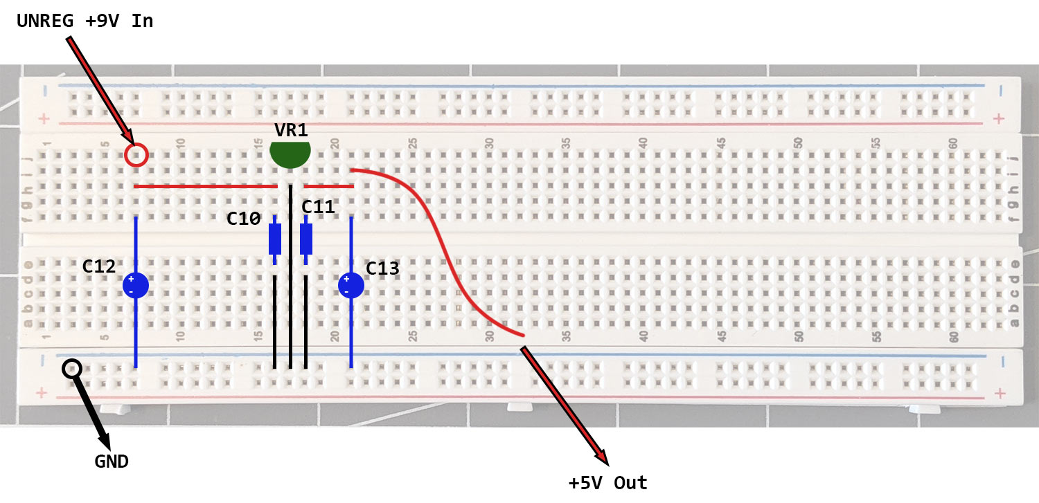

With my 9v battery attached to this circuit it was outputting 5.02 volts which was exactly what I was hoping for. Because I'm new to this, it's still a pleasant surprise when a component behaves the way it's supposed to!
I then decided to take a look at how diode D1 was going to affect the voltage to the rest of the board. All I know about Diodes is they allow current in one direction and prevent current from travelling in the other but how does this affect voltage? More specifically, do they lower the voltage in the direction current is allowed? Only one way to find out. Test it.
With the diode in circuit my output voltage reading was 4.66 volts. So yes, the diode was costing me 0.36 volts. Do I need to be worried about that? The answer to this, like many other questions, was not forthcoming but I decided to remove it for initial testing and see what happened.
Once again, it was with great trepidation I wired my rats nest breadboard to my SixtyClone and switched on.

Holy shit. It freakin' worked!!!
I absolutely did not expect that. Seriously. And this time, no burning smells, no over heating, just a steady, sharp and colorful screen. I wish I could express in words just how good that felt.
Yes, ladies and gentlemen, I am proud to announce that I did indeed blunder my way to building a working prototype of a C64 RF Modulator replacement on a breadboard. And writing this a whole 48 hours after the event, I still can't quite believe I managed it.
 |
| Prototype - Revision A |
After the initial wave of shock and amazement passed, I was able to pass a more critical eye over what I was actually seeing over a solid hour or so of testing:
The Good
Colors were nicely saturated and accurate
Text was sharp with very little color smearing.
Only the voltage regulator got warm and never too hot to touch.
The Bad
Touching some of the wires on my breadboard caused interference and interruptions to the video signal which meant the physical connections were crap.
The Ugly
It was a very, very noisy picture. This doesn't come out in pictures at all so you're just going to have to take my word for it, but the best way I can describe it is like a layer of colourful static with a slight magenta hue overlaying everything. This static was also swimming slightly.
Some Experimentation
So, obviously the first thing I can say with certainty is that diode D1 is not required. I didn't feel the need to put it back.
Next thing I did was re-seat some of my wires. I also reduced the length of the "luma out" wire which was causing the most interference when I touched it and this definitely helped reduce the interruptions to the signal at the expense of making the wire tighter than I would like. It did reduce the noise however.
I then had a think about the chroma signal. I know from my social media intake that the s-video output from a C64 isn't standard and many people who build their own cables (and I've watched them do it on YouTube) incorporate a resistor into the chroma line. I have not built my own s-video cable, and have no idea if such resistor is present in the one I bought, and I'm not about to take it apart to find out either. In the advertising blurb of the cable however, it does state "has modifications to improve picture quality and reduce audio hum" which probably means it does. What I know for certain is that in my chroma circuit, the final resistor in the chain before the signal leaves the board and heads to the cable is R4 and is 180 ohm, as specified in the schematic. I wanted to see what happened if I changed the value of this resistor.
I removed the 180 ohm resistor and replaced it with a 330 ohm resistor. This categorically made the picture worse and emphasised the existing noise. I removed that and inserted a 100 ohm resistor. That categorically improved the picture and whilst the noise was still very much present, it stopped swimming and was definitely cleaner, or at least de-emphasised.
I did the same with the last resistor on the luma circuit, R7, and at 330 ohm it started to lose sync and the picture started to scroll. No bueno. Back went the original 150 ohm resistor
During my research I came across this video by Adrian Black. The whole video was fascinating: not only his revelation that there are far more revisions of C64 RF Modulator in the wild than the two schematics in the Service Manual would suggest, but also his honing in on the need for the inductor (L1) in the chroma circuit. The message in that video was unequivocal - it is not needed and its existence in the circuit actually causes blurring in the video output. He also demonstrated that L1 was not present in PAL versions of the modulator, only in NTSC versions. Why on earth would this be?
The eminently sensible and easy to follow answer was actually in a comment by Craig Sherman under the video: it was put there to meet strict FCC requirements and was done "to help reduce dot patterns when watching the RF output on a B/W TV and to eliminate adjacent channel interference... By eliminating the choke [another term for inductor] you are allowing the chroma signal to have as much 'sharpness' as the luma."
I love it when a technical question comes along and is answered in plain English that makes perfect sense. As a result I doffed my cap to those with far more knowledge than me and I simply removed inductor L1 from my build. This also meant, I supposed, that I could remove capacitor C1 from the build too: an inductor and capacitor together like this in a circuit is called a "Band Pass Filter": the inductor impedes high level frequencies from the circuit; the capacitor impedes low level frequencies. This leaves the mid level frequencies to get through. But as we are removing one I figured the other isn't required either. So I waved bye bye to C1. Removing these in my breadboard definitely cleaned things up a bit, though I can't say my picture was blurry in the first place. What I categorically did notice was a reduction of color noise throughout, leaving just a plain static noise overlaying the picture.
I also experimented by removing capacitor C6. This has the effect of disconnecting the chroma circuit from the composite circuit, which would mean the composite signal would just be black and white - not really a problem as I'm only using the luma and chroma circuits for s-video output. I wanted to do this however, to determine if this connection was somehow feeding back into the luma circuit and creating unwanted noise. In either case it didn't matter, removing it made no difference and given that if I ever wanted to use composite I'd rather it was color, C6 stays in.
This leaves my schematic looking like this:

Nothing I did above completely eliminated the ever present "static" noise I was encountering though. Now, whilst this noise was far from ideal, I do have to put on record that I could easily live with it if necessary - the video out from my janky as f*** breadboard was by now actually remarkably good all things considered and the noise I'm complaining about isn't visible during fast moving demos for example, only on solid colours.
I then wondered if breadboards are inherently "noisy" themselves? It strikes me that flippin' great tangles of cheap wire with tenuous connections literally hanging out all over the place couldn't possibly be good for a sensitive TV signal? I Googled it and very quickly came across this forum post from where I found the following piece of wisdom, posted by AndyC_774:
"I dislike breadboards, and stripboard isn't much better. Both are good ways to hook a few parts together quickly to check that they work more or less as expected, in a very rough & ready way. Once you start looking for accuracy, quietness and precision, they very rapidly become your worst enemy"
Now this is very obviously confirmation bias, but I really do believe, at this stage, that the "static" noise I'm seeing is because of the breadboard and not the design. All my decoupling capacitors are in place as specified and no amount of tinkering on my part improved things any further. I could however, easily be wrong, I frequently am, but I don't think I can address the noise issue any further without taking the breadboard out of the equation.
I can scarcely believe it myself but I actually think my prototype, and with it Phase 1 of this project is complete.
 |
| Janky As F**K (JAF) |
So. It's time to move on from the breadboard, and actually design a PCB. Holy shit. I never, ever thought I'd get to say that!
Queue hours and hours of Googling and YouTube watching.
After a great deal of this I decided the software I was going to use to design my PCB was KiCad because it comes very highly recommended, there are plenty of tutorials on YouTube, and it's open source which is important because I really don't want this project to necessitate a mortgage. That aside, I'm under no illusions. This is going to be a real steep learning curve (have I mentioned I've never done anything like this before?) and I do not doubt this will be something of an ordeal!
In the next entry, I will let you know how I get on.
Before closing I confess to being a bit ill at ease with my existing transistors at Q1 and Q2 (2SC1684T). Not because they don't work - they actually seem to work perfectly - but rather because the only place I could get them was bloody Ebay and at a hugely over inflated price (£5 each!) so I'm going to research different transistors that I can easily obtain from Digikey at a much more sensible outlay.