Showing posts with label Build. Show all posts

Friday, 18 March 2022

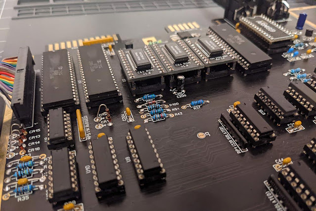
250466 SixtyClone IC Replacements


If you've read my entries here, here, here and here, you will be well aware that I have, of late, been spending some time building and experimenting with a "SixtyClone" Commodore 64, a modern reproduction of the famous 80's home computer.

Part of this whole undertaking was to see if this was possible with modern replacements for the original ICs (Integrated Circuits): the chips that make the whole thing tick.

In the final entry in that series, I came to the conclusion that, with my particular SixtyClone board, the 250466 variant, replacing the ICs was troublesome.

Since then, I've taken delivery of a few more replacement parts and it's worth noting down here what I've subsequently discovered. To save repeating myself, all tests were carried out by replacing one chip at a time, and with an ARMSID and PLAnkton in place. If, after installing the replacement, it booted correctly, I ran the following demos back-to-back to test:

  • Christmas Mega Demo
  • Eclectic
  • Edge of Disgrace
  • Star Wars

I also played:

  • Commando
  • Ghostbusters
  • My own (never-to-be-published-so-don't-even-ask) game which is a good test of sprite collisions.

Replacement 1 - TOLB


The first replacement I want to talk about is the TOLB (sometimes called "The Other Little Board" and which represents the number 8701 upside down). This is a substitute for the original 8701 chip and was developed by François Léveillé, aka Eslapion.

This was an easy replacement. Out came the original chip, in went the TOLB and it just worked. No glitches, no repeat of the strange sprite collision behaviour I encountered with DIYChris's 8701 replacement (which itself is based on a design by Jeff Birt). All demos and games displayed and behaved normally.

Cost: £10.99 + £3.35 Shipping =£14.34  from Retroleum

Replacement 2 - SaRuMan SRAM


Cost: £12.99 + £2.12 Shipping = £15.11 from Retroleum.

Another replacement developed by François Léveillé. This was very interesting. For the first test I removed the TOLB and put back the original 8701 chip. Then removed original RAM and inserted the SaRuMan.


Oh dear. Back to the strange character issue that initially plagued me when I tested another type of replacement RAM. Much research revealed that other replacement utilised SRAM that was rated at 12ns,  much too fast for this old computer. The SaRuMan however was rated at a more tolerable 55ns so I did not believe this error was the same and at no stage did it replicate the "constant restore" issue I encountered. And indeed, I had partially expected this, again, from information gleaned while (obsessively?) scouring forums, and in this case, a comment by Mario Bernardo (aka SX64 Man) under this YouTube video:

" ... I also had the same exact issue with the Saruman and 6567R8 VICs in 250466 NTSC and PAL boards only. The Saruman however works fine with the 6567R9 or 6569R5... If I recall correctly, the exact "weird character" issue you saw in the video with the Saruman is due to some of the different RAS timings on some of the earlier C64 board revisions and earlier VICs. "

If this was correct, replacing my 6569R3 VIC with a 6569R5 (which I was planning to do anyway) would cure this issue.

This segues very nicely to:

Replacement 3 - 6569R5


Cost: €24.37 + €0.61 PayPal Fees + €8.20 Shipping = €33.18
From Poly.play.com

Like the TOLB, this replacement was easy. It just worked. It did not however, make any improvement what-so-ever to jail-bars or smearing and so picture quality remains acceptable but far from perfect.

With this in place however, it was time to test the SaRuMan.

It freakin worked!

Yup, with the 6569R5 VIC-II the SaRuMan behaved exactly the same as normal RAM. No weird characters, no odd behaviour at all. Obviously I was delighted but without an oscilloscope I could not confirm why. I got in touch with the developer, François Léveillé who has very kindly replied and advised:

 "It looks like the CPU clock coming from the 6569R3 is 'offset' relative to the AEC signal and this causes the R/W signal, when low (CPU performing a write) to stay low for a brief period INTO the VIC-II access portion of the cycle.

The C64C (250469) is protected from this problem because the DRAM R/W signal is passed through the large 64 pin PLA."

All Replacements Together

With the original chips removed and the SaRuMan, TOLB and now the 6569R5 in place, the C64 works perfectly. All demos and games played with no issues and as far as I can tell the computer is behaving exactly as one would expect. Happy days.

So what have I learned so far about modern replacements in my SixtyClone 250466?

  • 12ns SRAM does not work.
  • The Jeff Birt 8701 replacement, and derivatives, are incompatible with something, as yet unknown.
  • My 6569R3 VIC-II does not work with SaRuMan.
  • SaRuMan will work with 6569R5 VIC-II.
  • TOLB works.
  • ARMSID works.
  • PLAnkton works (but note: as of June 2024 these have been discontinued.)
  • RECOM replacement 5V and 12V voltage regulators work.
  • I am shit out-of-luck if I want all black replacement parts.
Remember, this is simply what I've found with my particular combination of board and parts. Your results may very well vary with different parts and PCB.

My working build. Shame about all the green.


What's Next?

As far as ICs are concerned, this leaves the CIAs; 6510 CPU and VIC as the only main chips left to replace - nothing is going to happen here for a long time. I still await a new keyboard and again, this may be a long-time before anything transpires.

I have however, recently acquired a Cartridge Guide (yes, that's what it's called, not a shield, not a port cover - it's all in the Service Manual, part number: 326116). Once again, I was not able to source one of these new, though I am certain they have been refabricated for use in, for example, the Ultimate-64-Elite, but for whatever reason they are not for sale separately. As it was, for £1.95 + £2.12 shipping, I was able to obtain a salvaged one from Retroleum


I spent 5 or 6 hours with wet and dry (starting with 240 grit going up in gradual stages to 2000 grit) to remove some of the pitting, scuffs and blemishes accrued over the last 30 years but I'm not bringing it to a mirror polish because I want lacquer to stick.


After a thorough degreasing and clean up with 0000 grade wire wool, I then applied six coats of black lacquer. I finished this off with T-Cut scratch remover to completely smooth the lacquer and give a bit of bling. The finish is beautiful and this picture doesn't do it justice.


For the record, I did experiment with Gun Blue to blacken this but it did not take properly so whatever sort of steel this is, something prevents the selenium dioxide in the Gun Blue from reacting. I would have preferred something far more durable like a powder coating but my budget simply doesn't extend that far so lacquer will have to suffice. I will solder this into the board sometime in the near future.

I have also been intrigued by the idea of getting my new C64 online. And yes, this is possible (after a fashion - we won't be streaming YouTube videos though!), and yes, I've bought something which, all being well, will make getting online possible. The complete story forms my next entry which you can read here.

Running Costs Update

Total costs for everything in this update are as follows:

£14.34 + £15.11 + €33.18 (£29.09) + £4.07 = £62.61 ($76.16 or €71.42).

Add this to my running total of Commodore related expenditure and I am now at:

£820.30, or $1104.22 or €976.56


Thursday, 10 March 2022

The Trials of Building a Commodore 64 in 2022 (Phase 4)


PART 12 - TROUBLESOME UPGRADES

From Phase 1 of this saga you will be aware that another part of this exercise was to use, where possible, all new parts. Up till now I had been using an ARMSID, replacement ROMs, PLAnkton and a MOS 8701 replacement all through initial testing. With this combination of replacements there was one troublesome issue that cropped up now and again but we will touch on that a little later. As my initial build kit included all the logic ICs and RAM, I had been using new-old-stock 41464 RAM ICs but with a stable build, now was the time to test the SRAM replacement I had bought.


This was a very quick, and pretty definitive test. It didn't work. On switch-on the screen was peppered with random characters and no cursor. We couldn't proceed any further in that state so the original RAM chips were re-inserted and everything returned back to normal.

The problem here is that I wasn't sure if the SRAM replacement was faulty, or if it was failing because it was conflicting with something else on the board. I had assumed the former, and had resigned the replacement SRAM to scrap when I watched YouTuber Jan Beta's video of his experiences doing virtually the same thing, with the same board. A link to his video.

In that video, Jan experienced exactly the same "weird character" glitch as I experienced, except in his case the SRAM was conflicting with his prototype VICII Kawari. When he put his regular VIC chip back (a 6569-R3 - the same as mine) everything returned to normal. This obviously doesn't translate exactly to my experience but it did get me wondering.

Jan was using Eslapion's "SaRuMan" SRAM replacement. I had a different variation of SRAM. Jan also had a different 8701 replacement, the "TOLB" (The Other Little Board), also by Eslapion. If we assume the different SRAMs work the same way (a naïve assumption I'm afraid) then all other things being equal, the only difference between Jan's set up and my own was the 8701 replacement. Jan said at the start of the video that he had to remove his initial 8701 replacement as it was causing a strange issue with Sprite collisions. As it happens, I had been experiencing odd behaviour in Sprite collisions too.

In 2021 I was messing around with Assembly Language and managed to write a slightly crap, but functional game which my son and I have been thoroughly enjoying trying to beat each other's speed run times. In the game I use sprite-to-sprite collisions to trigger further actions (yes I know it's not good code but for pity's sake, I'm a beginner!). Anyway, on my breadbin this runs perfectly, but in the new build the sprites visibly overlap somewhat without any action being triggered as though somehow, something is misaligned. I wondered then if the 8701 replacement was the cause of the fault here?

Luckily I had a new-old-stock 8701 I could drop in and experiment with.

Installing the original 8701 chip did indeed cure the sprite collision problem: that immediately behaved as one would expect.

I then added the SRAM replacement.  The "weird character" problem was gone! Only to be replaced with an equally bad, if not worse problem of constantly resetting, or probably more accurately, constantly "restoring" the computer, which on boot sat at a flickering ready prompt - no "64K RAM SYSTEM 38911 BASIC BYTES FREE" message - no, just a flickering, unresponsive screen with "Ready" in the top left corner, as pictured below. The exact same screen you get when hitting "run/stop" and "restore", but flickering and clearly stuck in a loop. Without an Oscilloscope I have no clear idea what's going wrong.


Putting the 41464 chips back in brought everything back to normal. So yeah, another wrong theory.

I put some time into reading some fairly heated forum posts about SRAM replacements and it's clear some designs just aren't compatible with the 250466. I think it's obvious I have bought one of them: cue some colorful language which I will spare you here.

Further digging brought me a comprehensive answer. In a forum post here, in reference to the SRAM replacement design my problematic one is based on, Eslapion states:

"He used a 12ns high speed cache SRAM IC which is very sensitive to the slow transition signal of old 8 bit computers and this causes write errors. This makes this design unreliable. The fix is to use a slower 45ns/55ns IC which uses less power and correctly takes slower signals. This problem is more prevalent on the 250466 because it uses legacy 74LS technology to manage the multiplexed address bus. The 469 uses the large 64 pin PLA which uses HMOS/CMOS technology and has sharper transitions"

Looking at the SRAM chip on the board I bought (pictured above) we can see it sports an IS61C1024AL-12HLI chip. And looking at the spec sheet for this chip, lo and behold, it does indeed have 12ns access time:


Bugger. So there we have it - a sensible explanation for the very clear problems I encountered. None of this was obvious and another case of Caveat Emptor. I simply bought an allegedly compatible product, which was (and still is - so watch out!) sold as being compatible with the 250466, based on aesthetics and put no more thought into it than that. Oops. So, yeah, back into the scrap pile it goes.

I will pick up a SaRuMan in the near future and test with that but I'm pretty confident this is the answer. As for the 8701 replacement it seems a fair bet that Eslapion's "TOLB" will work too so I'll add that to the "to buy" list.


PART 13 - IS "ALL NEW" ACTUALLY POSSIBLE?

So far, this doesn't look good for my "all new" philosophy: incompatible SRAM and a glitchy 8701 replacement. I now understand the issue with the SRAM. However, there are a number of other things we must try in order to understand exactly where incompatibilities with the 8701 replacement lie: is it glitching because it is simply not 100% compatible, or are other replacement parts (the ARMSID, PLAnkton or something else) having a reaction and it's that particular combination that's causing the glitch?

My gut feeling (and this is something I can eventually test) is that the 8701 replacement is glitching because of the Voltage Regulator replacement I'm using. The 8701 is fed, via the inductor at L1, from the CAN +5 volt line which comes directly from the 5v regulator at VR2 which, as stated in Phase 1, I replaced with a Recom R-78B5.0-1.5. If so then something about the design of the 8701 replacement reacts to that 5v input differently than the original chip which works perfectly. At any rate, it's a theory.

This causes me to raise a hitherto unanswered question: as more and more replacement chip projects start to see the light of day are the developers creating these with other replacements in mind? Are full tests being undertaken with every conceivable combination of every replacement already available on every variant of every new and old PCB in both NTSC and PAL flavours? I think the answer to this is, and always will be, unsurprisingly, no.

Given that there are several variants of an 8701 replacement, and half a dozen replacement SIDs, at least that many replacement PLAs and who knows how many replacement PCBs all of which work in slightly different ways, it's a distinct possibility that an "all new" C64, is not actually possible. At the bleeding edge of 80s technology, we will have to act as beta testers and, it's clear already that things aren't completely satisfactory. (Edit from the future: ok, I was wrong. All new is possible, but it's not cheap!)

In order to fully test future incompatibility questions, I would have to test all possible combinations of replacement parts against each other, and against original chips as a baseline. I don't have a spare suite of original chips to conduct that and I'm not that keen on messing about with my perfectly functioning new build just in case I royally screw up. However...

Brace yourself for a lightbulb moment.

I do have a recently discarded and completely broken PCB with shoddy sockets that, if brought back to working order, could serve as the ideal test bed for precisely these kind of experiments.

I had, literally, thrown that broken PCB away. It was sitting in a bag, outside in the garbage where I had rashly dumped it in disgust after extracting the last few parts I needed for the new build. We have fortnightly garbage collections round these parts and it had not yet been collected.

Suffice to say, it's not in the garbage any more. I'm going to bodge it back to working order and it's going to have a working life as a test bed for all future experiments. This, I think, is a fitting future and a satisfactory outcome, albeit one where ill fitting chips will always be an issue. So, the to do list for the broken board is:

  • Fix it
  • Replace salvaged components
  • Populate with ICs and replacements for test


PART 14 - THE NEW BUILD

As for the new build, as I write it's been running perfectly for 8 weeks or so now. I added to my already scandalous expenditure by getting an S-video to HDMI converter (a cheap one from Amazon) and together with a nice long HDMI cable and a C64 s-video cable this has improved the video substantially from the horrors of composite. It's a long way from perfect - nothing is perfectly crisp, jail-bars are pretty bad, fast moving sprites smear but as I said in Phase 1 it's good enough.

I'm actually very impressed with this cheap HDMI converter. It's simple to setup - there are two button on the output side (not pictured): one of these switches between composite and s-video input; the other cycles through HDMI output resolutions and holding that button down for a moment cycles between 4:3 and widescreen aspect ratios which is very handy indeed.

Strangely, it is fixed to a 60Hz output but in practise I see no ill effects from feeding in 50Hz from the Commodore.


PART 15 - PICTURE QUALITY

To give you some idea of what I'm talking about regarding picture quality, I've taken pictures of  the screen output with all 16 colors. This will demonstrate the sort of degradation I'm talking about. This is output via S-video to HDMI using the converter above to a 2010 Samsung LE32C450E1W LCD TV and photographed with a DSLR. The colour reproduction here is hit and miss because I didn't bother to white balance, but it's the jailbars I want to highlight. You can click any of the pictures for a larger view:


PART 16 - SUMMING UP

First let's update the running cost total with new expenditure from the purchase of the HDMI Converter which was £34.99 ($42.36 USD or €39.91) from Amazon UK. This brings total costs so far to:

£757.69, $1028.06, €908.14

With luck, a fair wind and yes, more money to throw at it, maybe the next 12 months will see a brand new keyboard, a 6569-R5 (and I do wonder if that will make the slightest difference to jail-bars and sharpness - I'm not hopeful), a SaRuMan SRAM replacement and a TOLB 8701 replacement, but that aside, for the moment, I fully intend to simply enjoy the computer I've built.

Now, how about a nice game of chess?


(There is nothing nice about how much I suck at this game!)


In the next article I source some of the IC replacements I mentioned above and talk about these at (excruciating?) length.


Saturday, 5 March 2022

The Trials of Building a Commodore 64 in 2022 (Phase 3)


PART 7 - EVENTS SO FAR

So let's recap. In Phase 1 I detailed all the components I sourced and calculated the total cost to date. In Phase 2 I expanded on this by providing documentation to help in identifying parts, determining values, and their location on the board; then finally I explained the tragedy of how I destroyed all my hard work attempting to remove junk sockets that were the source of all the problems I was encountering.

I took a few days to get my head together about all of this. The way I figured it, I had 3 options:

  1. Give up, scrap everything and swallow the loss.
  2. Bodge a repair to the broken board.
  3. Start again.

In truth I only gave serious consideration to options 2 and 3. Ripped traces aren't the end of the world and with the correct application of bodge wire I could have it up and running again. But. I would have it up and running with all those junk sockets (coz there was just no way I was going to tackle de-soldering any more of them!).

However, with all the research I'd done, I had pretty much sourced suppliers for all the replacement parts I needed. Those parts which were not so easy to obtain (like the toroidal line filter at L4) I reckoned I could salvage from my broken board. Sure I would need to spend more cash on a new PCB and new components but, as I already had the case and all the ICs and accessories, which are by far the biggest expense, I figured I could restart for a semi-reasonable price.

It was a fairly easy decision in the end. I decided to scrap the broken board and start again.

There was no one supplier I could get everything from. In the end I used 5: Mouser, Digikey, Retroleum, Tindie (Bob's Bits) and RS Online.

Let's see how that worked out for me:


PART 8 - THE COST OF REBUILDING

From Digikey: DB9 controller ports, most of the capacitors, most of the diodes, fuse, fuse-clips, some of the transistors, power LED header, the L1 and L5 inductors and the 14, 18 and 20 pin sockets (Mill-Max brand, 110 series).

Cost of Components: £33.44

Additional Tax: £6.69

Shipping: Free

Total: GBP £40.13 (USD $53.78, EUR €47.98 )


From Mouser: the rest of the capacitors and diodes, the crystal oscillator, keyboard header and the rest of the Mill-Max sockets:

Cost of Components: £26.33

Additional Tax: £7.66

Shipping: £12.00

Total: GBP £45.99 (USD $61.64 , EUR €54.99 )


From Retroleum: all the remaining port connectors and a new power switch.

Cost of Components: £13.87

Additional Tax: -

Shipping: £2.35

Total: GBP £16.22 (USD $21.74,  EUR €19.39 )


From Tindie (Bob's Bits): the new PCB and the resistor pack.

Cost of Components: $55.50

Additional Tax: -

Shipping: $6.00

Total: USD $61.50 (GBP £45.87, EUR €54.84)


And finally from RS Online: 5v and 12v Voltage Regulator replacements.

Cost of Components: £15.81

Additional Tax: £4.15

Shipping: £4.95

Total: GBP £24.91 (USD $33.39, EUR  €29.78 )


PART 9 - A QUICK ASIDE

During this process I tried to buy leaded solder and to my astonishment, was prevented from doing so:


This was another are-you-f*****g-serious moment? Since when was this a thing? As it happens I know someone with a trade account and was able to use them to get it for me but others may struggle. Just putting it out there.

PART 10 - A VERY EXPENSIVE MISTAKE

Getting back to the rebuild costs, all the new components came to a grand total of (GBP, USD, EUR):

£173.12, $232.05, €206.98

and we add this to our previous grand total which was:

£549.58, $753.65, €661.25

Which gives a revised grand total of:

£722.70, $985.70, €868.23

That's the first time I've calculated all that so yeah, I'm going to need a moment to let that sink in. The Mega65 is looking pretty goddam reasonable right about now!


PART 11 - REBUILDING

Aside from a delay due to RS Online sending the wrong component - a pain but, in fairness, something they resolved perfectly well, the rebuild was completed once again over a week, and I undertook it in exactly the same way as the first build, with only one minor change. This time I vertically mounted the diodes at CR9 and CR12-16 which looks and feels much nicer.


And the new sockets? Absolutely stunning. They were comparatively expensive but worth every penny. Every single chip is being held in a vice like grip and, surprise surprise, on switching on for the first time, everything just worked. I felt like the conquering hero. Vindicated. All my woes and stresses just fell away. There are other 250466 SixtyClones, but this one is mine.


From a purely financial point of view, this whole exercise is, to put it mildly, utterly ridiculous. Even if I exclude the additional £173.12 it cost me to rebuild, the initial costs of, lets call it a round £550, are stupid. For all that money, I have merely recreated a 1980s computer, with no additional functionality, and with all the identical problems the original computers had. From a purely financial point of view, it's laughable.

I've gone to great lengths to lay out the financial cost because I want someone who's playing with the idea of doing this to know exactly what they're letting themselves in for; to prove, beyond any measure of doubt, that if you just want to tinker with a C64 then buying an original, second hand, is categorically, the way to go.

But, for me, none of this was about the money. This was a wholly technical exercise and personal ambition. I will (and do) get a tremendous amount of satisfaction knowing that this C64 only exists because my hands built it.

And on that, very satisfactory note, we can draw the curtain on Phase 3.

In Phase 4, with a fully functioning computer, we'll take a look at some chip replacements and the strange issues they present. Will the fun ever end?


Sunday, 27 February 2022

The Trials of Building a Commodore 64 in 2022 (Phase 2)


PART 5 – STARTING THE BUILD

In Phase 1, I outlined all the major components, where I bought them, and ran up a bill that certainly raised my eyebrow. In this phase I start to solder all of these components into a working machine, eventually. There is a lot to be said about how I got there and all is not plain sailing.

The site where I purchased the PCB contains a link to a Bill of Materials (BoM) which itself provided links to several online suppliers who can supply many of the required parts. This is very useful if sourcing your own components but note that many parts are hard to come by and available only on backorder with very long lead times. Do pay very strict attention to the components you've been linked to, to ensure suitability: whilst the values of the component may be correct, the pitch (the distance between the centres of the pins) may not be so be doubly careful.

For your reference and to help in identifying parts, I have written, and include below, an illustrated guide of all the internal components required to complete the build (minus the PCB and ICs) and for convenience, this includes a copy of the original list of parts for the 250466 from the C64/C64C Service manual.


250466 Illustrated Component Guide

The kit of PCB components I bought also came with a BoM which listed the parts included and their location on the board. This is extremely helpful. You must however take the time to methodically go through each component against the BoM to ensure everything is present and correct.

A magnifying glass is extremely helpful here to ensure you are accurately determining, for example, resistor band colours. As you can perhaps see from the above picture I segregated all components according to their reference on the PCB and made a note of the component values too. This is not a job to rush! Once separated and annotated I put all components into their own individual bags which kept them safe and separate until soldering time.

The C64/C64C Service Manual contains parts lists, schematics and board layouts for several PCB revisions, including the 250466 I'm building, though it must be said the readability of the service manuals available online is pretty poor. For that reason I have redrawn the board layout for the 250466 (click for a full sized image 6288 x 3090 pixels) which is labelled with the location of each part.


A copy of this layout is also included in the 250466 Illustrated Component Guide (link above). If you prefer a more interactive component locator, Eduardo Arana has created a magnificent page, linked here, which allows you to select a particular component from a drop down menu and the resulting location is clearly highlighted on a graphic of the board.

I have also redrawn the 250466 schematics, again because scans available elsewhere are of very poor quality. Click for full sized images (6932 x 4516 pixels which can be printed very large should you desire):

1 of 2:


2 of 2:


Monday, 14 February 2022

The Trials of Building a Commodore 64 in 2022 (Phase 1)

INTRODUCTION

This is quite the departure from my other posts. And the reason for this lies squarely at the door of Covid. The pandemic and lockdown meant I wasn't getting out with my camera and as a consequence, my attention moved to projects I could undertake at home. This change of focus seemed quite natural to me - computers have been a part of my life since the 1980s and the urge to do something with that had always been there and the pandemic was the perfect opportunity to build on that. Literally.

When I decided to build a brand new Commodore 64, the first thing I did was hunt around the internet for any helpful guides to aid in the process. Whilst they may be out there, I didn’t manage to find a “one stop shop” of information. There are, however, a good number of separate resources which help.

My intention here is to pull together this information, as I understand it, to produce a simple resource for anyone who might wish to do the same or who simply has an interest in what it takes to build a 1980s 8-bit computer in the 2020s.

I will discuss the equipment required to undertake the build; the necessary parts that need to be obtained; where I bought them and total cost (correct at time of writing - I will include the actual price I paid – in the currency of supplier as well as a running total cost converted to EURO, GBP and USD using current conversion rates to give a broad idea of actual cost) as well as my honest thoughts and insights as the build progresses. 

The first question to address is why? Why would I want to build a 40 year old computer now? The answer is simple: fun. I enjoy learning stuff in a practical way and I would get a real kick out of using a computer I had built myself.

DISCLAIMER

Everything was bought with my own money and I am not sponsored by any of the suppliers mentioned. I do not endorse any supplier mentioned here.

Where there is a % after a cost this means that I purchased more than one item from that supplier and the cost shown for shipping or tax is a percentage of the total cost of that particular purchase (e.g. if I bought two items from one supplier then the shipping cost shown against each item are 50% of total shipping cost).

BEFORE BUILDING

Before we start soldering anything, it’s important to understand what it is we’re actually going to construct and the limiting factors.

First we are limited by the parts we can obtain. We need:

  1. A case and accessories.
  2. A PCB.
  3. All the components for the PCB.
  4. A keyboard.

Let’s look at each of these in turn.


PART 1A. THE CASE

Whilst we might have a working bunch of electronics at the end of the day it’s neither practical, sensible or complete without a case and as I write this (in January 2022), there are presently only two options available which I would consider:
  1. A second hand, original case (Breadbin or C64C variant).
  2. A new C64C variant.
There are pros and cons to both but bear in mind the option you go for here, should dictate the next step which is the PCB you choose.

I wanted to use, at all stages, new parts where possible, but, contrary to what you may have heard or read it is NOT possible (at this time) to build a 100% new Commodore 64. However, it was my initial intention to keep salvaged parts to the absolute minimum.

With this stated, I will start the build by obtaining a brand new C64C style case:


Supplier: https://icomp.de/shop-icomp/de/shop.html

Cost of Case: €47.16 EUR
Additional Tax %: €8.96 EUR
Cost of Shipping %: €9.93 + €26.80 = €36.73 EUR
Total Cost of Item: €92.85 EUR

Running Total (in GBP, USD, EUR): £77.07, $105.85, €92.85
Personal Comments on Item.

Getting this case from the supplier in Germany to my home in Scotland was a costly exercise. There was a prohibitively high minimum order value to ship directly, caused by, the supplier says, new UK legislation following Brexit. In order to circumvent this I used the services of a German-based international shipping and forwarding company (myGermany) and thus incurred additional shipping expenses (which is why there are two values under costs of shipping - €9.93 from supplier to shipping company and €26.80 from shipping company to me). However, although very expensive and somewhat convoluted the process was swift taking only 8 days from ordering to taking delivery.

As regards quality of the product, I would describe it as fit-for-purpose. There are a number of quite noticeable and ugly marks on the case, this one in particular was prominent and quite disappointing, but it is merely cosmetic - not a crack:


However, in all fairness the supplier clearly states on their website: 

“Due to the modern plastic, the choice of colours and the old molds, binding seams and sprues are visible for production reasons (see photos). This becomes most visible on darker colours. The desired variety of colours was more important to us and ultimately outweighed the perfection of the visual appearance. We would like to emphasize that the imperfections are not a sign of bad production quality, but of the genuine toolings that are now 35 years old. Detailed plastic flow analysis just wasn't invented in 1986!”

I will deal with, and disguise, this ugly mark later in the build. Also included are 8 screws to mount the PCB and two white rubber feet. I will be replacing both the screws and the feet. The screws seem poor quality and the feet… Well, I’m definitely not using white feet!

PART 1B. KEYBOARD MOUNTS

AND POWER LED

If I had been using a second hand Breadbin case, keyboard mounts would not be necessary. But we’re not. So it is. This is an essential element to our build and should be considered part and parcel of the case as it is used to screw mount our keyboard securely within. There are several options available here:
  1. Buy salvaged part
  2. 3D Print a new part
  3. Buy a new part
As the same supplier I purchased the case from also supplies keyboard mounts, I made life simpler for myself by purchasing these at the same time as the case. Costs shown below are calculated via % of total cost of order.


Supplier: https://icomp.de/shop-icomp/de/shop.html

Cost of Mounts: €14.42 EUR
Additional Tax %: €2.74 EUR
Cost of Shipping %: €3.03 + €8.20 = €11.23 EUR
Total Cost of Item: €28.36 EUR

Running Total (in GBP, USD, EUR): £100.6, $138.18, €121.21

Personal Comments on Item

These are very sturdy, excellent quality steel mounts which will easily outlive the computer, and me. They are a perfect fit in the selected case. Screws to mount the keyboard are supplied but strangely, rather than a more common Phillips head, these are hex screws requiring an Allen Key (also supplied) to fit which seems like one more thing to lose.

Power LED

Traditionally the Breadbin C64 had a red power LED. The C64C appears to have come with either green or red LEDs probably depending on the PCB that was used (my conjecture). For this build we are departing from tradition and going with my preference which is blue. Modern replacements in all hues are available from any number of suppliers but again my selection was simply a personal aesthetic decision.

Supplier: https://www.retroleum.co.uk/

Cost: £3.50 GBP
Additional Tax %: -
Cost of Shipping %: £0.27 GBP
Total Cost of Item: £3.77 GBP

Running Total (in GBP, USD, EUR): £104.37, $143.34, €125.73

PART 2 – THE PCB

The Commodore 64 was in production between 1982 and 1994 and during this time, both the case, and the PCB inside, underwent some fundamental changes. As intimated in Part 1, the case changed from the familiar and iconic breadbin design to the sleeker, but arguably less beloved C64C design, whilst inside the PCB also went through a number of iterations, driven, ultimately, to reduce costs by reducing the number of components.

In recent years, some of those PCBs have been recreated, with the specific intention of reviving broken machines and undertaking new builds. It’s not my intention to list every PCB variation Commodore produced for the C64, nor to list all of the new variants which are now available as there are many: from straight reconstructions of the originals to modern interpretations with added functionality. My thinking was to keep things as simple for myself as possible and of all the variants available I decided on the 250466 PCB design. This has the following benefits:
  • It was originally designed for a C64C case
  • It has a reduced chipset minimizing both cost and troubleshooting
  • It’s a longboard so still has all the chips I’m familiar with
  • It’s a popular board and as such there is some helpful information available

Supplier: https://www.tindie.com/products/bobsbits/sixtyclone-commodore-64-replica-pcbs/

Cost of PCB: $35.00 USD
Additional Tax: -
Cost of Shipping: $6.50 USD
Total Cost of Item: $41.50 USD

Running Total (in GBP, USD, EUR): £134.67, $184.84, €162.25

Personal Comments on Item

I would describe this “Sixty Clone” board as a work of art. With the black soldermask, white silkscreen and gold contacts it wouldn’t be out of place in a frame on the wall. It’s robust, chunky and the solder pads are a joy to work with, in my limited experience. The silkscreen is clearly marked for all components. The part of the PCB at the cartridge connector is too wide and some of my cartridges don't fit – the PCB will require filing down by a millimetre or so on each side. A surprising issue and one I'm not alone in encountering.

PART 3A – PCB COMPONENTS.

There are basically two ways to obtain the parts required to start this build – the hard way, and the easy way:
  • The hard way is to track down each component individually.
  • The easy way is to buy a pre-prepared kit.
For this build I initially took the easy way and this did not turn out well. I am not going to name the supplier (though there are a very limited number of companies that provide build kits of this type) and I have emailed to let them know of the problems I encountered and they have advised they will investigate stock from same batch which is fair enough. It is not my purpose here to bad mouth anyone, simply to relate my experience. Many others have had a positive experience and the company receives almost universal good reviews, so perhaps my experience was a one-off but I will speak about this later.

Supplier: not named

Cost of Pack: €82.45 EUR
Additional Tax: -
Cost of Shipping: €9.00 EUR
Paypal buyer security fee 5.4%: €5.12 EUR
Paypal Fee: €0.50 EUR
Transaction Costs: €0.50 EUR
Total Cost of Item: €97.57 EUR

Running Total (in GBP, USD, EUR): £215.65, $296.07, €259.82
Personal Comments on Item

The package itself should contain everything except the large ICs (Integrated Circuits) to complete the build, including all resistors, capacitors, filters, connectors and logic chips.

The pack I received was missing a 390 ohm resistor meaning I incurred an additional expense of £1.24 (pack of 20) to complete the set. Not a disaster and I didn't bother to complain to the supplier about this, but merely state this as fact. This brings our running totals to:

Running Total (in GBP, USD, EUR): £216.89, $297.77, €261.31

It is very difficult to say if this pack was value for money. What I can say with certainty is that buying this pack, from this supplier made the job of sourcing many disparate components ridiculously easy and (though I have not done the math) I suspect, after factoring in shipping costs of sourcing individual parts myself, buying the pack would be the most economic method. I am unsure as to the quality of the materials received not being overly familiar with them. The resistors in the pack were 5% tolerance and had I sourced these myself I would have sourced 1% tolerance. However, if we look at the parts list from the original service manual it states:


So what I’ve been supplied is exactly to spec.

There were a few inconsistencies worth mentioning with items received versus items listed in the BoM. The BoM specified 5% tolerance Inductors at L1 and L5, what was received were 10% tolerance; and the Timer IC LM556 specified was replaced with a NE556. None of this is problematic.

The round pin IC sockets I was supplied were an absolute disaster. Given what transpired later in the build I should have gone with my initial gut instincts which certainly had me questioning their quality simply based on their quite rough appearance, but having never compared a “quality” IC socket with a “standard” IC Socket I was ignorant of the consequences and I will pay for this ignorance later on.

PART 3B – MAIN ICs

To complete the PCB Build I still needed to obtain:
  • 2 x CIA
  • Basic, Character and Kernal ROMs
  • 6510 Microprocessor
  • VIC-II
  • SID
  • PLA
There is no lazy way to obtain these and each must be sourced individually. This is easy enough though and supplier, costs and additional info are itemised below:

CIA (COMPLEX INTERFACE ADAPTER)

Edit. Since this was first written, things have moved on and as of August '23, Jani's J-CIA project mentioned below is complete. The J-CIA can be purchased here. I have installed a pair in my SixtyClone and my own succinct overview is here.

There is no as-yet-available modern replacement for these and so they must be obtained from salvage. I am keeping my eye on the progress of both the XIA project by Jim Drew at cbmstuff.com, and the J-CIA project by Jani Laatikainen at 1nt3r.net/j-cia/. These projects looks like they will eventually produce a modern replacement for our CIAs but the ongoing chip shortage is delaying progress significantly.


Supplier: https://www.retroleum.co.uk/

Cost: £35.90 GBP
Additional Tax %: -
Cost of Shipping %: £2.79 GBP
Total Cost of Item: £38.69 GBP

Running Total (in GBP, USD, EUR): £255.58, $350.78, €307.74

ROMS (BASIC, CHARACTER AND KERNAL)

Edit from the future: in 2025 I replaced these ROMs with versions from TheRetroChannel as I much prefer the look.

Modern replacements for these are plentiful. I merely chose these as I really like the aesthetic.


Supplier: https://diychris.com/index.php/shop/

Cost: $45.00 USD
Additional Tax: -
Cost of Shipping %: $18.59 USD
Total Cost of Items: $63.59 USD

Running Total (in GBP, USD, EUR): £302.00, $414.37, €363.7

6510 MICROPROCESSOR

Edit: since writing this, Jani Laatikainen's J-CPU project mentioned below is now (as of May-2024) complete and I have replaced the 6510. Please see my overview here.

There is no as-yet-available modern replacement for these and so they must be obtained from salvage. There is an interesting project which allows you to use a 6502 microprocessor but for this build I don't want to simply replace one old chip for another. A project I definitely do have my eye on though is the J-CPU project, again by Jani Laatikainen, details of which can be found at 1nt3r.net/j-cpu/, but it looks like it will be 2023 or 2024 before anything transpires.


Supplier: https://ebay.co.uk/

Cost: £19.95 GBP
Additional Tax %: -
Cost of Shipping %: £2.36 GBP
Total Cost of Item: £22.31 GBP

Running Total (in GBP, USD, EUR): £324.31, $444.93, €390.47

VIC-II (VIDEO INTERFACE CHIP II)

Edit: At the time of writing, there was no as-yet-available modern replacement for the VIC-II so they had to be obtained from salvage. The VIC-II Kawari project was coming very close to being a viable replacement but had been delayed by the global chip shortage. The Kawari eventually became available in November 2022 and I have since installed one in my SixtyClone. Read about that here.

I believe the 250466 would normally have been populated with the 6569R5 variant but at the time of build I was unable to track down an R5. For now I have settled for the R3 variant.


Supplier: https://ebay.co.uk/

Cost: £24.95 GBP
Additional Tax %: -
Cost of Shipping %: £2.36 GBP
Total Cost of Item: £27.31 GBP

Running Total (in GBP, USD, EUR): £351.62, $482.35, €423.24

SID (SOUND INTERFACE DEVICE)

There are a plethora of modern replacements available for the SID. One of the most respected is Bohumil Nováček's (aka Nobomi) ARMSID which has received almost universal praise and also has the added benefit of coming with a software utility which can very easily change the behaviour of the chip to mimic either the 6581 or the 8580 variations of the original. This is very useful if playing demo’s or games which were written with a specific variation in mind.


Supplier: https://www.retrocomp.cz/eshop

Cost: €31.00 EUR
Additional Tax %: -
Cost of Shipping %: €8.90 EUR
Total Cost of Item: €39.90 EUR

Running Total (in GBP, USD, EUR): £382.25, $524.41, €460.14

PLA (PROGRAMMABLE LOGIC ARRAY)

Edit from the future: in 2025 I replaced the PLAnkton described below (which is no longer available anyway) with the NeatPLA, which has given me no issues at all and is only available in black. This is the way.

The original MOS variation of this chip has a very high and well documented failure rate. As a result, this is another chip which has a great many modern replacements available. Of these, one which received a great deal of positive feedback was the PLAnkton by Fredric Blåholtz (aka e5frog) and Francois Leveille (aka Eslapion) which appeared to have no compatibility issues that I could find. My only criticism: it was on a green PCB and stuck out like a sore thumb on my board. As it was, this irritation evaporated when Eslapion announced, in June 2024, that the last ever PLAnkton had been sold and these would be no more. The Xilinx CPLD doing all the hard graft (the XC9536XL) was discontinued when Xilinx was bought up by AMD and this prompted Eslapion to call it a day. As a consequence, if you're reading this after June 2024, you need to look for something else.

Supplier: https://www.retroleum.co.uk/

Cost: £12.50 GBP
Additional Tax %: -
Cost of Shipping %: £1.75 GBP
Total Cost of Item: £14.25 GBP

Running Total (in GBP, USD, EUR): £396.50, $543.94, €477.24

PART 3C – ADDITIONAL REPLACEMENTS

It was stated in PART 1A that, where possible, I want to use new parts rather than salvage. This is important to me as I don’t want the building of new machine, to mean sacrificing an old one. As it stands however, with the VIC-II, the CIA and the CPU there is simply no alternative currently available and salvage is the only recourse. There are currently projects on-going to produce modern alternatives for all of these but some appear to have stalled and given the global chip shortage currently being experienced, it’s not clear to me when these will see the light of day.

That said, there are a few more modern replacements I can throw at this build to ensure I am sticking with my original intent. These are:
  • MOS 7701/8701 Replacement
  • SRAM Memory Replacement
  • 5v and 12v DC Switching Regulators
  • RF Modulator Replacement (for Audio and Video Out)
I discuss these below but I do have more to say on this in a future post so stay tuned for my ramblings.

MOS 7701/8701 Replacement

The 7701 (NTSC) or 8701(PAL) is the chip which generates the dot and color clocks for the VIC-II. The original has a reasonably high failure rate which has driven demand for a modern replacement and there are many now available. The particular one I selected was chosen for no other reason than convenience (I was buying other items from that supplier) and aesthetics (let’s keep it to black shall we?). However, as you will discover later, this particular variant did not work properly.


Supplier: https://diychris.com/index.php/shop/
Cost: $17.95 USD
Additional Tax: -
Cost of Shipping %: $7.41 USD
Total Cost of Item: $25.36 USD

Running Total (in GBP, USD, EUR): £415.01, $569.30, €499.56

SRAM Memory Replacement


One of the most significant differences of the 250466 PCB to older variants is in the RAM. Where older PCBs utilised eight 8kByte RAM ICs, the board I have selected requires two 32kByte RAM ICs. And again, with time and age these chips fail. New old stock is still available and I am utilising these for the moment as my selected replacement (pictured) did not work. I initially selected a variant based on my “keep it black” aesthetic and no other reason, however come final construction it was clear this had fatal problems which I will discuss in future. However, for now my outlay was as follows:

Supplier: not named

Cost: $18.00 USD
Additional Tax: $4.30 USD
Cost of Shipping %: $3.50  USD
Total Cost of Item: $25.80  USD

Running Total (in GBP, USD, EUR): £433.85, $595.10, €522.26

5v and 12v DC Switching Regulators

This is perhaps the most controversial replacement being made in this build. The original parts 7805 and 7812 are no longer manufactured but can still be obtained as salvage or new old stock. Direct replacement parts are still available but after having undertaken some research and heard about modern replacements which do not generate anything like the same amount of heat my interest was piqued. I am not going to criticise the original parts – they are still in my original Breadbin and still working perfectly well after 38 years – there’s absolutely nothing to criticise! But for this build I’m in a position to try something new. The modern 5v Regulator (pictured) will not require a heatsink. For absolute clarity, the parts obtained were:
  • Recom R7812-0.5
  • Recom R-78B5.0-1.5


Supplier: https://uk.rs-online.com/web/

Cost: £15.06 GBP
Additional Tax %: £4.00 GBP
Cost of Shipping %: £4.95 GBP
Total Cost of Item: £24.01 GBP

Running Total (in GBP, USD, EUR): £457.86, $627.99, €551.08

RF Modulator Replacement

Edit from the future: the original component mentioned below wasn't the best. I pretty soon replaced this with a RF Mod replacement of my own design which was a significant improvement. However, when the HD-64 was released by Side Project Labs, which outputs a 1080p HDMI signal, it was a no-brainer to install that instead.

We need some way to get video out of the computer and the original Commodore 64 did this via an RF Modulator which processed the signals generated by the VIC-II and SID chips and modulated them, directing the signals to both the A/V out port and the RF out port.

The RF out port is all but redundant now – this took the signal from the computer and fed it into the aerial socket of your TV. You would tune your TV into the signal and this is how many people used their Commodore 64s in the 80s.

In 2022 I would never, ever use this method and only require use of the A/V socket which carries a composite signal and an early form of S-video signal. In the future we may not require this either but at the time of writing, the composite and S-video signals are all I require to ensure the build works and for initial testing. There are many and varied modern replacements for doing this but I have no need for anything complex at this time. Once again the basic RF Mod replacement I selected came down to simple aesthetics. This is a clone of Reinhard Grafl's (aka C0pperdragon) S-Video Bypass/RF Replacement:


Personal Comments on Item

I have used this variant of RF Mod replacement before and I feel it important to point out that if you are using Composite out with these don’t expect a quality picture! In my experience they are worse than the original RF modulator and introduce heavy jail-bars. S-Video is much improved, but still a long way from perfect and jail bars are still a blight, especially with certain colored backgrounds - red for example is a horror show. Such are the tribulations of old tech. There is much talk of the "lumafix" which is supposed to further reduce jailbars but as this sits between the socket and the VIC chip i doubt there is enough clearance in the C64C case and honestly, I'm just not that bothered. It's good enough until somebody figures out a decent HDMI connection to modern TVs.

Supplier: https://www.ebay.co.uk/

Cost: $18.00 USD
Additional Tax %: $4.30 USD
Cost of Shipping %: $3.50  USD
Total Cost of Item: $25.80  USD

Running Total (in GBP, USD, EUR): £476.69, $653.79, €573.78

PART 3D – ADDITIONAL SUNDRY ITEMS

Finally, these items were purchased not because they were necessary to have a working machine but simply to “improve” the build:
  • Replacement Screws for Case and PCB
  • Heatsink and Thermal Adhesive
  • Black Rubber Feet for case
  • Bespoke Case Sticker
  • Male and Female Pin Headers.
Very little needs to be said about the majority of this list. The screws are simply to replace the poor quality ones received with the case; the heatsink will be required by the VIC-II – it’s the only component left that will generate much heat and the black rubber feet are necessary because the white rubber feet supplied with the case would simply look ridiculous.

Total Cost including Shipping: £6.96

Running Total (in GBP, USD, EUR): £483.65, $663.33, €582.13

Of the two remaining items in that list, some more detail:

BESPOKE CASE STICKER


Supplier: https://www.stickersinternational.co.uk/

Cost: £16.00 GBP
Additional Tax %: £3.99 GBP
Cost of Shipping %: £3.95 GBP
Total Cost of Item: £23.94 GBP

Running Total (in GBP, USD, EUR): £507.59, $696.12, €610.86

The purpose of this is my attempt to disguise the nasty moulding marks on the case. This is a design I created myself but with fairly obvious influences! It is 66mm x 35mm on a brushed silver background. It achieves its intended purpose and I’m very happy with the look. Quite how durable it is remains to be seen but as the minimum order was four stickers, I have spares.

Male and Female Pin Headers

Supplier: https://www.amazon.co.uk/

Cost: £2.49 GBP
Additional Tax : £0.50 GBP
Cost of Shipping %: -
Total Cost of Item: £2.99 GBP

The sole purpose of these is to mount the RF Modulator Replacement and to make it easy to remove should other options come along in the future. With these I can simply lift it on and off with ease and they’re tight enough to hold securely in the meantime. At this price definitely not the best quality but easy to replace if this is a problem.

Running Total (in GBP, USD, EUR): £510.58, $700.22, €614.45

This concludes sourcing and purchase of all the PCB components, chips and miscellany.

PART 4 – KEYBOARD

The timing of my build is, perhaps, a little unfortunate. If I were to be writing this at the same time next year (2023) then my options may be a little wider but as things are right now, I have two sensible options as far as a keyboard is concerned:
  1. Mechboard64
  2. Salvaged original keyboard.
The Mechboard64 is a magnificent piece of work, utilising a bespoke PCB, a bespoke aluminium bracket, 3D printed key adapters, standard Gateron microswitches and (and this is the unfortunate bit) salvaged, original keycaps or 3D printed keycaps. This final point makes building a Mechboard64 pointless for me. I’ve not seen 3D printed keycaps of sufficient quality that I’d want to buy them and I would have to buy a keyboard, to obtain the keycaps, to build the Mechboard so… yeah, I’m buying a salvaged keyboard.


There are plans afoot for new keycaps as well as a completely new keyboard (Blingboard 64) to be manufactured at some point in the future but these are/will be crowdfunding campaigns and like all crowdfunding ventures, we cannot guarantee they will ever see the light of day. Indeed, reading the updates from Jim Drew on his keycap campaign over at Indigogo has been excruciating as problem after problem rears its head, however to be fair, Jim does appear to be handling every issue diligently and keycaps are finally getting out to backers.  Who knows if these will ever be available to anybody else however, and if they are, for how long? Future builders may well be shit out-of-luck getting these new. And the Blingboard is years away from being produced, if ever. Thus, if I ever want to be able to use this machine, then a salvaged keyboard is my only sensible option at the moment.

Supplier: https://www.ami64.com/

Cost: £39.00 GBP
Additional Tax : -
Cost of Shipping %: -
Total Cost of Item: £39.00 GBP

This completes the sourcing and purchase of all initial components. Of course additional costs will be incurred as upgrades and chip replacements become available.

TOTAL COST OF PARTS


Grand Total (in GBP, USD, EUR): £549.58, $753.65, €661.25

of which £101.93 ($139.83, €122.74) was simply on shipping.

In Phase 2, I start the build and encounter some show stopping issues.


Popular Posts